358 9424200994 Rev N
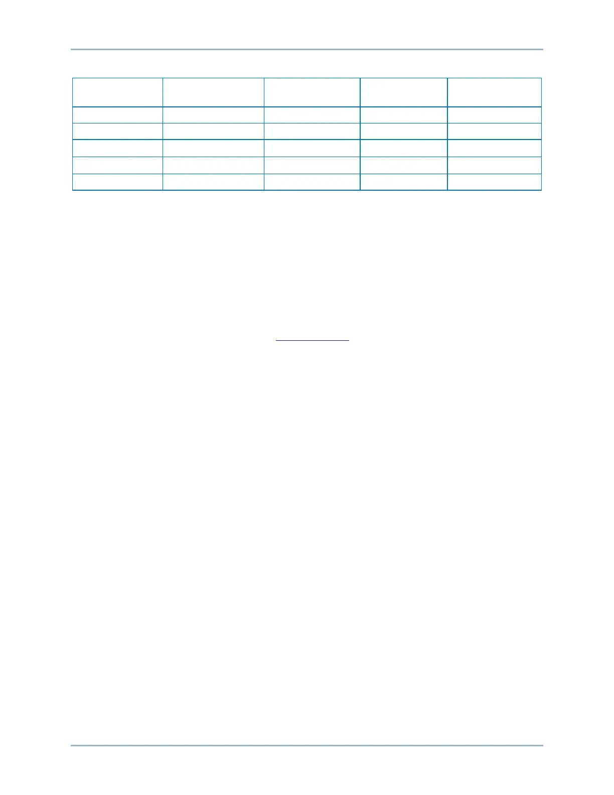
Table 119. Internal Compensation Chart
IEC Transformer Setup
The IEC setup table is aimed at describing transformers that use phase shifts and winding designs that
are more commonly found outside the US market. As can be found in the IEC standards, phase and
bushing names of U, V, W, will be used generally, rather than A, B, and C, or H and X. Specifying phase
shift and transformer connection is accomplished with the D-Y-Z + clock method. For instance, a
transformer connection will be Dy1 rather than a DAB/Y, though some dual designations will be used for
clarity. The number associated with the winding (Dy1) can be almost any hour of the clock, hence the
term “around the clock” phase shifting.
In transformer standards such as IEEE C57.12.00 and IEC-60076-1, there will be many variations on the
nomenclature and figures used to show how the phases are identified in a three-phase system. For
details on IEC transformer connections, go to www.basler.com
and download the technical paper titled
Three Phase Transformer Winding Configurations and Differential Relay Compensation, which was
presented at the 2004 Western Protective Relay Conference.
Use BESTCOMSPlus to open the System Parameters, Transformer Setup screen and select the IEC
Setup button. On this screen (Figure 274), you can setup Windings 1 and 2. Press the OK button when
finished.
Compensation
Ground
Compensation
A Phase B Phase C Phase
Wye (none) 0 = No I
I
I
Wye (none) 1 = Yes I
- I
I
- I
I
- I
DAB 0 = No or 1 = Yes
(I
- I
) / √3 (I
- I
) / √3 (I
- I
) / √3
DAC 0 = No or 1 = Yes
(I
- I
) / √3 (I
- I
) / √3 (I
- I
) / √3
DDAB 0 = No or 1 = Yes (I
A
- 2I
B
+ I
C
) /3 (I
A
+ I
B
- 2I
C
) /3 (-2I
A
+ I
B
+ I
C
) /3
Configuration BE1-11g