T 6 Installation
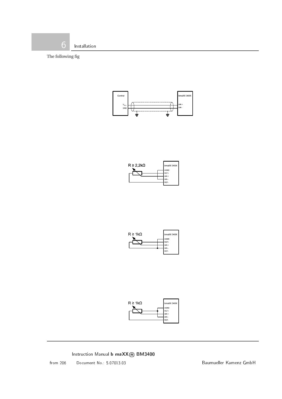
The following figures show some examples how to connect the analog input. While selecting the potentiome-
ter pay attention to the maximum load of the reference voltage output (10mA) and to the input impedance of
the analog input (3,5kOhm).
• Providing an analog set value by a control.
U
SE T
may have values between + 10V and -10V related to GND.
Figure 6.40: Variable voltage from a control at the analog input
• Providing analog set values using a potentiometer and both reference voltages.
By connecting the potentiometer between REF+ and REF-, voltages in the Range of -10V (REF-) and
+10V (REF+) related to AGND can be adjusted at the analog input.
Figure 6.41: Va riable voltage from reference voltages at the analog input
• Providing analog set values using a potentiometer and the positive reference voltage.
By connecting the potentiometer between AGND and REF+, voltages in the Range of 0V (AGND) and
+10V (REF+) related to AGND can be adjusted at the analog input.
Figure 6.42: Variable voltage from positive reference voltage at the analog input
• Providing analog set values using a potentiometer and the negative reference voltage.
By connecting the potentiometer between REF- and AGND, voltages in the Range of -10V (REF-) and
0V (AGND) related to AGND c a n be adjusted at the analog input.
Figure 6.43: Variable voltage from negative reference voltage at the analog input
100
Instrution Manual
b maXX
®
BM3400
from 206 Doument No.: 5.07013.03
Baumueller Kamenz GmbH
 Loading...