Terminals at the front of the ontroller b oard 6.13T
6.13.3 Analog inputs and outputs
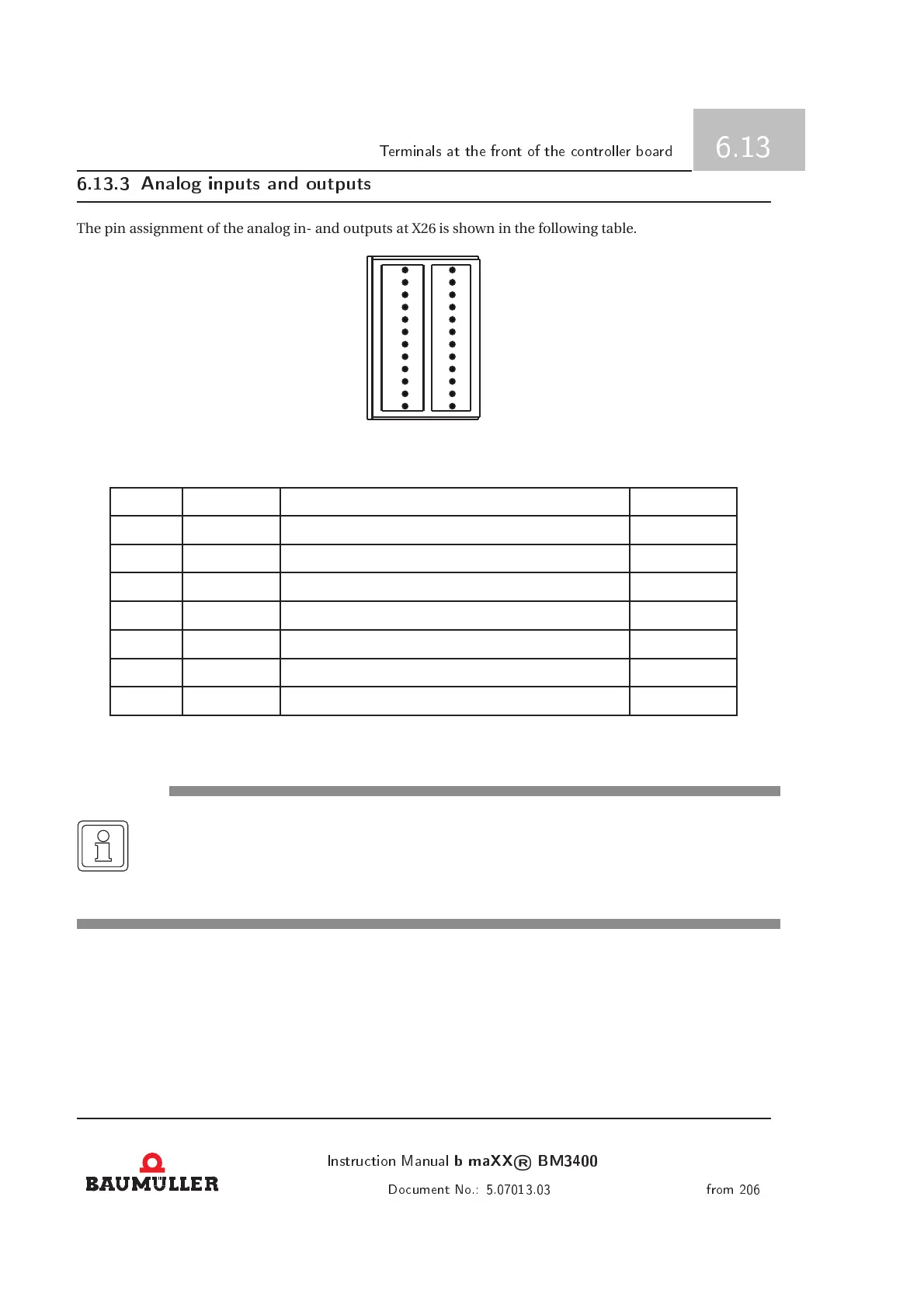
The pin assignment of the analog in- and outputs at X26 is shown in the following table.
1
2
3
4
5
6
7
8
9
10
11
12
13
14
15
16
17
18
19
20
21
22
23
24
Figure 6.39: P lug-in connector X26
Pin-no. Connection Meaning Limit values
1 AOUT1 Analog output 1 (PELV/SELV) I
a
= 10mA
2 AGND GND for analog I/O (PELV/SELV)
3 AOUT2 Analog output 2 (PELV/SELV) I
a
= 10mA
4 REF+ Reference output +10V (PELV/SELV) I
a
= 10mA
13 AIN+ Analog difference input + (PELV/SELV) ±10V
14 AIN- Analog d ifference input - (PELV/SELV) ±10V
15 REF- Reference output -10V (PELV/SELV) I
a
= 10mA
NOTE
For connecting analog inputs and outputs you must absolutely use shielded cables with two-
sided applying of the screen to PE.
At an improper or missing screening you may reckon, that there will be great EMC problems!
Instrution Manual
b maXX
®
BM3400
99
Doument No.: 5.07013.03 from 206
 Loading...