Terminals at the front of the ontroller b oard 6.13T
6.13 Terminals at the front of the ontroller b oard
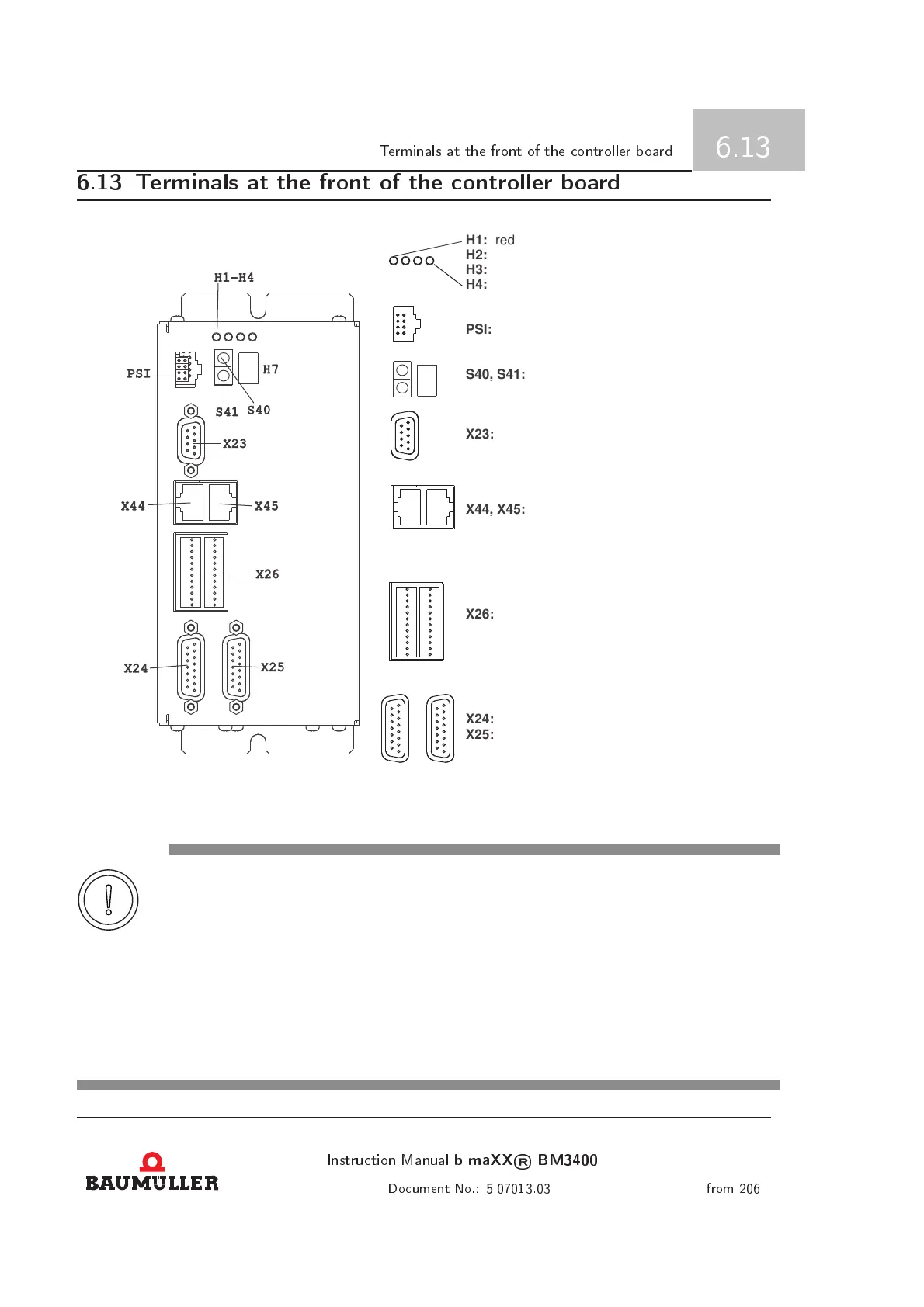
H1-H4
PSI
X44
H7
S41
S40
X23
X45
X26
X24
X25
H1:
H2:
H3:
H4:
PSI:
S40, S41:
X23:
X44, X45:
X26:
X24:
X25:
red: current limit
yellow: negative torque direction
orange: positive torque direction
green: life sign
interface for Baumüller memory module
address selection
LED status display
RS232
inputs, outputs, control signals
encoder 2
H7:
CAN (CANopen, CANsync)
encoder 1
Figure 6.30: connections of the controller board
CAUTION
The following c an occur, if this safety note is not complied with:
• Damage to property
The danger is: Electricity. Connector assignments, which do not accord to the device connections,
can lead to damage on the device or on connected peripherals.
In the following chapters some pins of c onnectors are labeled as Not assigned. The correspond-
ing counter part must not be connected. It can not be assumed, that the corresponding pin is
not connected internally. Allways use connection cables with connection assignments which
exactly accord to the assignments of the device.
Instrution Manual
b maXX
®
BM3400
91
Doument No.: 5.07013.03 from 206
 Loading...