T 6 Installation
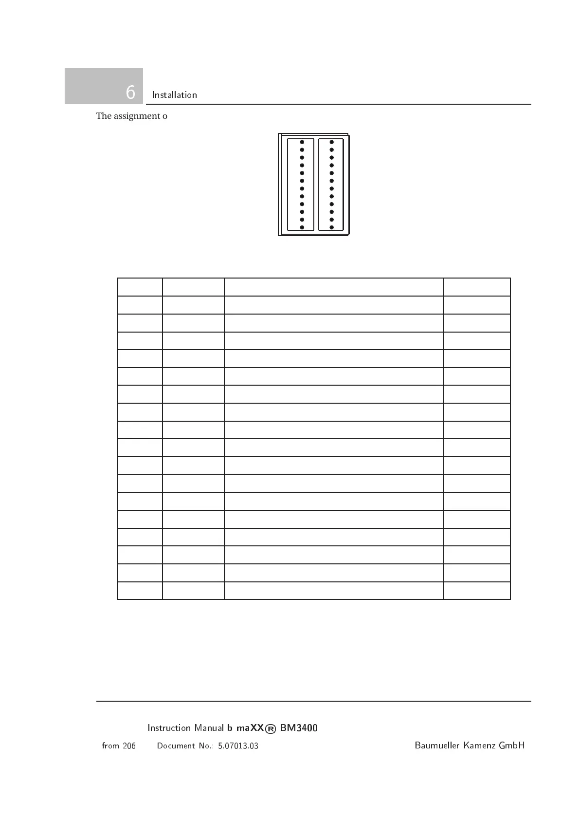
The assignment of the digital in- and outputs at X26 c a n be seen in the following table.
1
2
3
4
5
6
7
8
9
10
11
12
13
14
15
16
17
18
19
20
21
22
23
24
Figure 6.38: Plug-in connector X26
Pin-no. Connection Meaning Limit values
5 24VIO 24V-Supply for digital I/O (PELV/SELV)
6 DIN1 Digital input 1 (PELV/SELV) I
I N
= 2mA
7 DIN2 Digital input 2 (PELV/SELV) I
I N
= 2mA
8 DIN3 Digital input 3 (PELV/SELV) I
I N
= 2mA
9 DIN4 Digital input 4 (PELV/SELV) I
I N
= 2mA
10 SH Quickstop input (PELV/SELV) I
I N
= 2mA
11 IF Pulse enable input (PELV/SELV) I
I N
= 2mA
12 GNDIO GND for digital I/O (PELV/SELV)
16 DOUT1 Digital output 1 (PELV/SELV) I
a
= 0.6A
17 DOUT2 Digital output 2 (PELV/SELV) I
a
= 0.6A
18 DOUT3 Digital output 3 (PELV/SELV) I
a
= 0.6A
19 RELS Relay output, NO contact (P ELV/SELV) 60V / 1A
20 RELW Relay output, center (PELV/SELV) 60V / 1A
21 RELO Relay output, NC contact (PELV/SELV) 60V / 1A
22 BBO Ready for use relay output, NC c ontact (PELV/SELV) 60V / 1A
23 BBS Ready for use relay output, NO contact (PELV/SELV) 60V / 1A
24 BBW Ready for use relay output, center (PELV/SELV) 60V / 1A
98
Instrution Manual
b maXX
®
BM3400
from 206 Doument No.: 5.07013.03
Baumueller Kamenz GmbH
 Loading...