Home
Baumuller
Power Tool
BM4400
Page 188 (Terminals BM4755)
Baumuller BM4400 - Terminals BM4755
360 pages
Manual
Save Page as PDF
To Next Page
To Next Page
To Previous Page
To Previous Page
Loading...
Wiring diag
rams
Instruction handbook
b maXX
BM4400, BM4600, BM4700
Document No.: 5.1200
8.07
Baumüller Nürnber
g GmbH
188
of 358
7.10
7.10.2.8
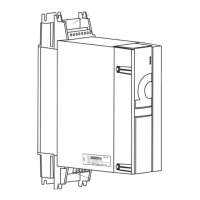
Terminals BM4755
Figure 89:
Electrical connec
tions for p
ower supply, motor, ... for BM4755
187
189
Table of Contents
Main Page
Table of Contents
3
1 General
9
Information on the Instruction Handbook
9
Key to Symbols
10
Limitation of Liability
11
Copyright Protection
11
Other Applicable Documents
12
Spare Parts
12
Disposal
12
Guarantee Provisions
12
Customer Service
13
Terms Used
13
List of Other Applicable Documents
13
2 Safety
15
Contents of the Instruction Handbook
15
Changes and Modifications to the Device
15
Usage for the Intended Purpose
16
Responsibility of the Operating Company
17
Protective Devices
18
Training of the Personnel
19
Personal Protective Equipment
20
Special Hazards
21
Fire Fighting
22
Safety Equipment
23
Conduct in Case of Danger or Accidents
23
Signs and Labels
24
Signs and Labels BM4X1X
25
Signs and Labels BM4X3X/BM4X4X
26
Signs and Labels BM4X5X
27
Signs and Labels BM4X6X, BM4X7X
28
Type Code Labeling
29
3 Technical Data
31
Dimensions
31
Dimensions BM441X
32
Dimensions BM442X
33
Dimensions BM442X-S/A
33
Dimensions BM442X-F/C
34
Dimensions BM4X3X
35
Dimensions BM443X-S/Z, BM443X-A/F
35
Dimensions BM443X-C, BM463X-F
36
Dimensions BM4X4X
37
Dimensions BM444X-S/Z, BM464X-S/Z
37
Dimensions BM444X-A/F, BM464X-A/F
38
Dimensions BM4X5X
39
Dimensions BM445X-S/Z, BM465X-S/Z
39
Dimensions BM445X-A/F, BM465X-A/F
40
Dimensions BM465X-FXX-3XXXX and BM475X-FXX-3XXXX
41
Dimensions BM465X-FXX-3XXXX-RYY, BM475X-FXX-3XXXX-RYY
42
Dimensions BM465X-ZXX-3XXXX-[RYY], BM475X-ZXX-3XXXX-[RYY]
43
Dimensions BM4X6X
44
Dimensions BM446X-S/Z
44
Dimensions BM4X7X
48
Weight
50
Operating Requirements
51
System Types
51
Requirements to the Energy Supply / Supply System
52
Motor Requirements
54
Required Environmental Conditions
55
Correction Factors if the Operating Conditions Are Changed
56
Mounting Height
56
Environmental Temperature
57
Supply Voltage
57
Coherence between Rated Current and Peak Current
59
Calculation of the Thermal Rms Current
59
Coherence between Peak Current and Rated Current
59
Cooling
61
Electrical Data Basic Units
63
Electrical Data of the Universal Units
63
Electrical Data BM441X Universal Units
63
Electrical Data BM442X Universal Units
66
Electrical Data BM443X Universal Units
70
Electrical Data BM444X Universal Units
73
Electrical Data BM445X Universal Units
76
Electrical Data BM446X Universal Units
79
Electrical Data BM4X7X Universal Units
82
Electrical Data BM46XX Acceleration Units
84
Electrical Data BM4632 Acceleration Units
85
Electrical Data BM464X Acceleration Units
87
Electrical Data BM465X Acceleration Units
89
Electrical Data BM466X Acceleration Units
91
Electrical Data BM47XX Continuous Current Units
93
Electrical Data Power Modules
96
Electrical Data BM442X Power Modules
96
Electrical Data BM443X Power Modules
98
Electrical Data BM444X Power Modules
100
Electrical Data BM445X Power Modules
102
Electrical Data BM446X Power Module
104
Additional Data Referring to Water-Cooled Brake Resistors
106
Output Frequency Dependent Continuous Current Derating BM4XXX
112
Output Frequency Dependent Maximum Current Derating BM46XX
113
Overload Monitoring Modes
114
4 Design and Operation
115
Functioning
116
Controller
117
Standard Controller
118
ES Controller
121
Encoder Modules Slot/Position a and B
123
Interconnect Devices
124
MIX Mode BM443X Generation 1 and 2
124
Type Plate
125
Type Code
126
Explanation Type Code
126
Explanation Version Code
130
UL Notes
131
Display and Operation Elements
132
Leds
132
7-Segment Display
135
Address Switch S1 - S4 (Only es Controller)
136
5 Transport and Packaging
141
Safety Notes for Transport
141
What to Observe When Transporting
141
Transport Inspection
142
Unpacking
142
Disposal of the Packaging
142
6 Mounting
143
Safety Notes
143
Preparing for Mounting
146
Drilling Patterns
147
Drilling Patterns BM441X
147
Drilling Patterns BM442X
148
Drilling Patterns BM4X3X
148
Drilling Patterns BM4X4X
149
Drilling Patterns BM4X5X
150
Drilling Patterns BM4X6X
151
Drilling Patterns BM4X7X
153
Mounting Instructions
155
Requirements Mounting Plate for Cold Plate
162
Connecting the Water Cooler
162
7 Installation
163
Safety Notes
163
Voltage Test
165
Demands on the Power Supply
166
Connection Instructions at Special Power Supply Systems
167
Requirements to the Connecting Cables
168
Protection of the Device and the Cable
168
PE Connection and RCD Compatibility
169
Installation Requirements with Regard to EMC
169
Requirements for the Motor Temperature Sensors
170
Installation Procedure
171
Wiring Diagrams
173
Connection Diagrams
173
BM44XX, BM46XX, BM47XX (Basic Units)
173
BM44XX, BM46XX, BM47XX Power Module
176
Terminal Overviews
180
Terminals BM4412, BM4413
181
Terminals BM4414
182
Terminals BM442X
183
Terminals BM443X, BM463X
184
Terminals BM444X, BM464X
185
Terminals BM445X, BM446X, BM465X, BM466X
186
Terminals BM466X, BM476X
187
Terminals BM4755
188
Terminals BM447X, BM4773
189
Electrical Connection Power Unit
191
Requirements for the Screwing
194
Controller Terminals
195
Encoder Connection Slot/Position a and B
203
Analog Input Slot/Position D and E
218
Digital Inputs Slot a to E/Position D
220
8 Operation
223
Safety Notes
223
Operating Concept
224
Enable Signals
224
Power on Switching Frequency / DC Link Charging
225
Power Supply Switch-On Frequency BM441X and BM442X
225
Power Supply Switch-On Frequency BM443X (Generation 1)
225
Power Supply Switch-On Frequency BM443X Generation 2, BM4X4X to BM4X7X
226
Calculation of the Maximum Permitted External Capacity
227
Effects of the Different Charging Circuits
228
Table of Charging Times
228
9 Troubleshooting and Fault Correction
229
Behavior in Case of Malfunctions
229
Monitoring Functions
230
Fault Detection
234
Error Handling
238
Error Reset
239
Error Parameters, Error Messages, Error Reactions
240
Error Messages (2Nd Level)
241
Sub-Error Messages (3Rd Level)
250
Warnings
258
10 Maintenance
261
Safety Notes
261
Environmental Condition
262
Inspection Intervals - Maintenance Notes
262
Periodic Maintenance
264
Repairs
266
11 Accessories and Spare Parts
267
Cabling
268
Cables Power Supply-Device
268
Cables Device-Motor
270
Cable Control Voltage Supply/Signals
271
Interface Cable RS232
272
Fuses
273
Fuses BM441X
275
Fuses BM442X
277
Fuses BM4X3X
280
Fuses BM4X4X
281
Fuses BM4X5X
284
Fuses BM4X6X
288
Fuses BM447X
292
UL Fuse in the Ballast Circuit
293
Extra-Low Voltage Protection
293
Mains Filters
294
Block Diagram of Filter for Mains Applications (Simplified)
294
Baumüller Mains Filter Type Code
294
Required Mains Filter Environmental Conditions
294
Electrical Data Mains Filter
295
Mains Filter Selection
298
Power Chokes
300
Baumüller Accessories
304
Shielding Clamp
304
Cable RS232
304
Accessories Ethernet/Ethercat
305
Accessories - Canopen
306
Encoder Cables
307
Design Cover and Connectors
312
12 Shutdown, Storage
313
Safety Instructions
313
Requirements to the Executing Personnel
314
Shutdown
314
Demounting
314
Storage Conditions
315
Recommissioning
316
13 Disposal
317
Safety Notes
317
Disposal Facilities/Authorities
319
Appenidx a - Abbreviations
321
Appenidx B - Declaration of Conformity
323
Declaration of Conformity
323
B.1 Declaration of Conformity
323
Appenidx C - Safe Stop
327
Methods to Avoid an Unexpected Starting
327
Safe Torque off (STO)
330
Safety Classifications and Safety Notes
330
Function Principle STO
333
Shutdown Paths
334
C.2.2.1 Shutdown Paths
334
Sequence Diagram
335
C.2.2.2 Sequence Diagram
335
Connection Diagrams
338
C.2.2.3 Connection Diagrams
338
Safe Stop
340
Safety Categories According to en ISO 13849-1
340
C.3 Safe Stop
340
The Safety Relay
341
Application Example for Machine of Category
342
Application Example for Machine of Category
344
Application Expansions
346
C.3.5 Application Expansions
346
Requirements on an OSSD Test Pulse
349
Technical Data Safety Relay Module
350
Table of Figures Table of Figures
353
Table of Figures
353
Index
355
Overview of Revisions
357
Document No.: 5.12008.07 of
358
Related product manuals
Baumuller b maxx BM4400
82 pages
Baumuller b maXX BM4 Series
82 pages
Baumuller b maXX BM1000
176 pages