Safe stop
Instruction handbook b maXX BM4400, BM4600, BM4700
Document No.: 5.12008.07
335
of 358
E
Shutdown
path B
Pulse enable at BM4000 controller LC3
The safety function pulse enable is active, if no voltage is applied to the input terminals
(X3-3/5). The pulses for IGBT control are inhibited.
24 V must be applied to the available terminals (X3-3/5), to deactivate the safety function.
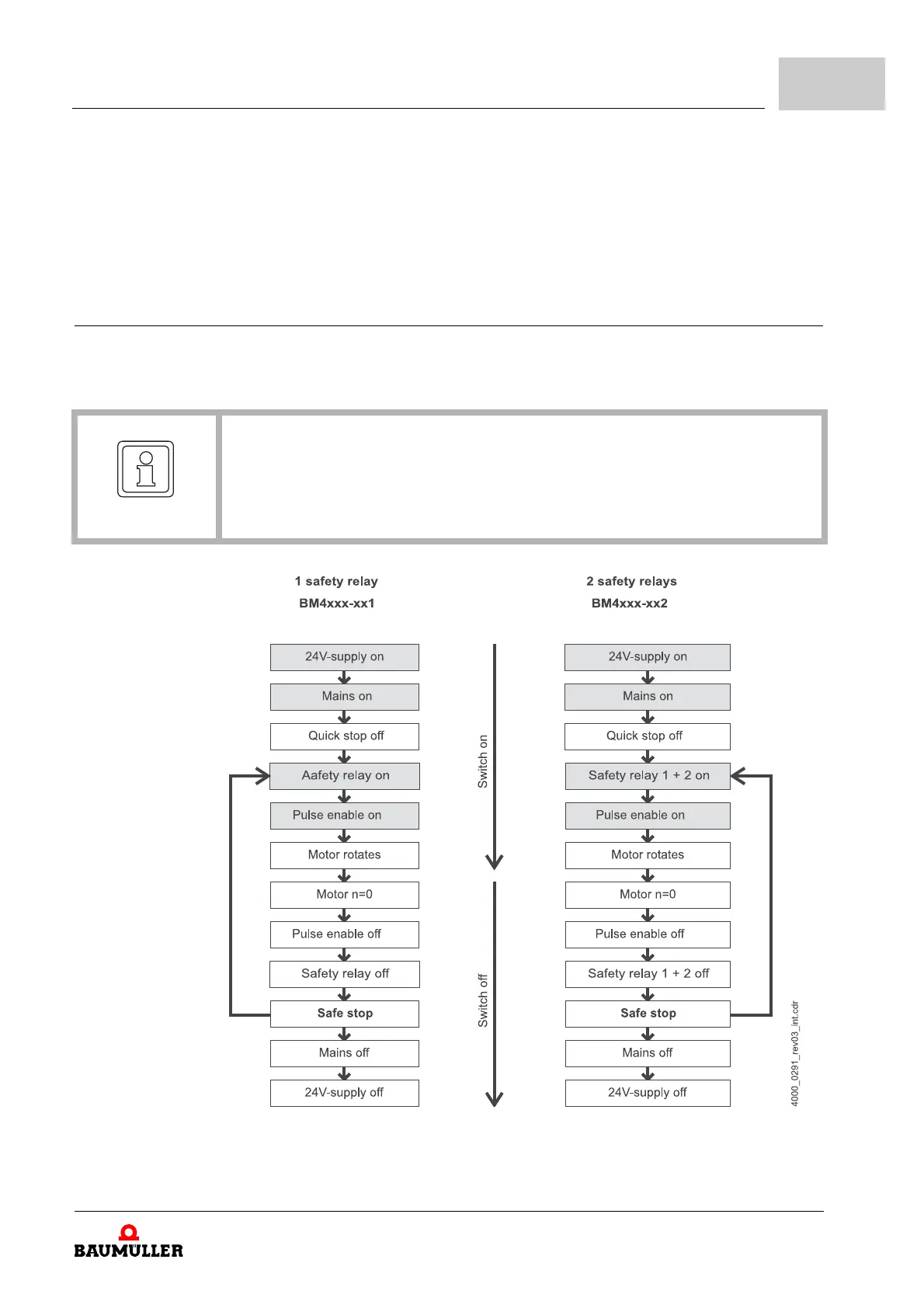
C.2.2.2 Sequence diagram
The starting and the shutdown sequence of the release signals and of the safety relay must be
considered, in order to assure a faultless operation of the drive.
Figure 111: Sequence diagram of 1 or 2 safety relays
NOTE
The safety function must be checked, before commissioning the machine, in which
the BM4000, with the safety function STO is installed. For this purpose a protective
function must be enabled (for example door contact). The motor must be with zero-
torque.