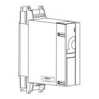
Installation
Instruction handbook b maXX BM4400, BM4600, BM4700
Document No.: 5.12008.07
173
of 358
7
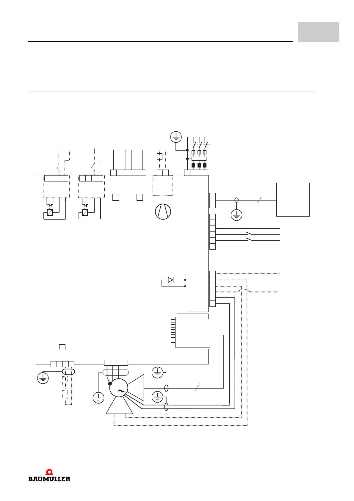
7.10 Wiring diagrams
7.10.1 Connection diagrams
7.10.1.1 BM44XX, BM46XX, BM47XX (basic units)
4000_0059_rev12_int.cdr
X3-3
X3-2
X3-1
X3-4
X3-5
X3-6
X101-2
X101-1
X101-3
X101-4
X101-5
X101-6
9
15
3
M
R
S3
X1
L1
L2
S1
S2
X1
A
PE VUW
X36-L
X36-N
B
M24V
X102-2
X103-2
X100-2
X100-3
X100-4
X100-5
X100-6
1U2
1V2
1W2
PE
BM4-ENC-XX
+24V**
+24V
+24V
M24V
M24V
PC
ProDrive
SUB-D, 1:1
1U1
1V1
1W1
PE
ENC
X100-1
Ba+
1C1
1D1
Ba-
X102-3
X103-3
X102-4
X103-4
X102-1
X103-1
+24V**
230 V
*
M24V
M24V
+24V
+24V
Motor temperature
bra
Mains bus
Ballast bus
Figure 77: Connection diagram with a directly controlled motor brake - basic units