101
6-847718-00 Rev. B00
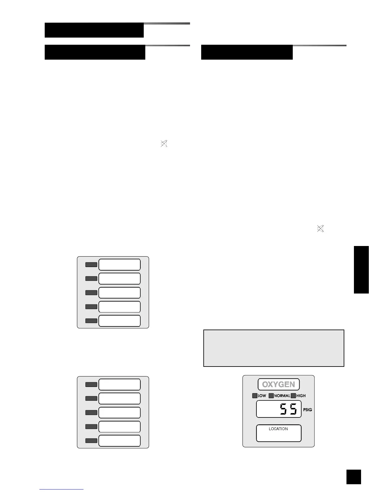
Digital display modules monitor pipeline
pressure or vacuum.
• The LED display indicates pipeline
pressure or vacuum.
• If piping pressure or vacuum level is
within high and low alarm limits, green
NORMAL indicator is illuminated.
• If pressure or vacuum level drops to, or
below, low alarm set-point, audible
alarm activates and red LOW indicator
flashes.
• If pressure or vacuum level rises to, or
above, high alarm set-point, audible
alarm activates and red HIGH indicator
flashes.
• When front panel alarm MUTE
button is pressed, audible alarm is
silenced. Alarm indicator remains
illuminated, but does not flash.
• Visual indicator will remain illuminated
as long as alarm condition remains.
• If audible alarm repeat time has been
set, audible alarm will reactivate, and
visual indicator will again flash after
specified time.
NOTE:
Sensor faults will be displayed as
-- FF 11 --
,
-- FF 22 --
,
-- FF 33 --
or
-- FF 44 --
error codes. Refer to trou-
bleshooting section for details.
Monitoring Mode (Cont.)
Operation
Digital Display Module
• If all signals assigned to an LED are
normal (switch contacts closed), green
indicator for gas service is illuminated.
• If an alarm occurs on any signal
assigned to an LED (switch contacts
open), audible alarm activates and red
indicator for gas service flashes.
• When front panel alarm MUTE
button is pressed, audible alarm is
silenced. Alarm indicator remains
illuminated, but does not flash.
• Visual indicator will remain illuminated
as long as alarm condition remains.
• If audible alarm repeat time has been
set, audible alarm will reactivate, and
visual indicator will again flash after
specified time.
Figure 95: Digital Display Module
LED 1
LED 2
LED 3
LED 4
LED 5
Figure 93: Multiplexer Module
LED 6
LED 7
LED 8
LED 9
Signal 5
Figure 94: LED Module
Multiplexer / LED Module
 Loading...