51
6-847718-00 Rev. B00
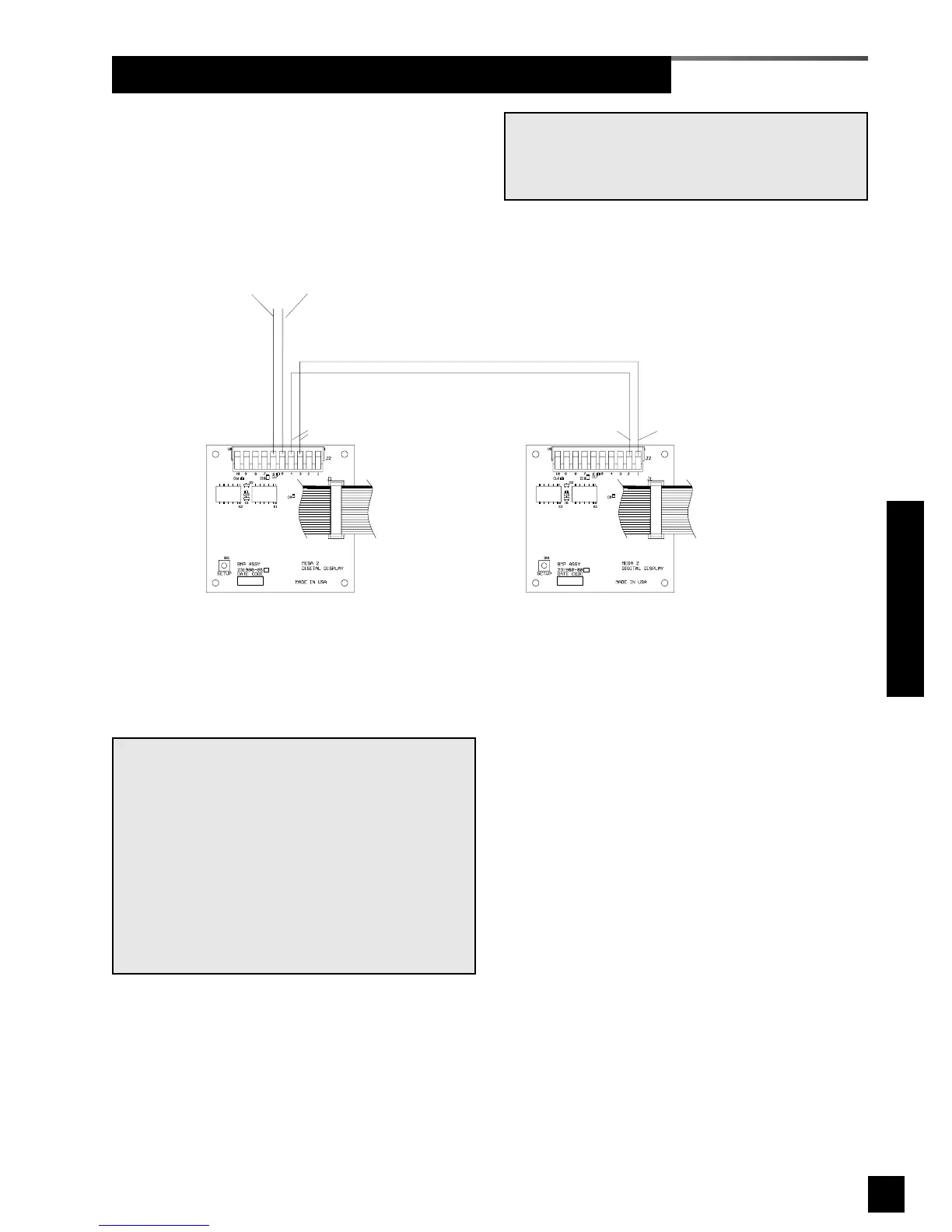
Wiring Schematic 6: Digital Display Module Master/Slave
Digital Display Module
at master alarm panel
Digital Display Module
at slave alarm panel
Signal from
sensor module
Pin 5 (+)
Pin 6 (-)
Master output
to slave
Pin 4 (-) / Pin 3 (+)
Slave input
from master
Pin 1 (+)
Pin 2 (-)
20 wire
ribbon cable
to adjacent
module
20 wire
ribbon cable
to adjacent
module
NOTE:
The above master to slave wiring configuration
DOES NOT comply with NFPA 99 wiring guide-
lines for two required master panels.
If digital display modules are used for a master
alarm, EACH master panel must be directly con-
nected to a sensor module for each pressure/vac-
uum service.
Additional panels, if desired, may be connected
as indicated above.
NOTE:
Field wiring cable shields must be grounded at
only one end, inside alarm panel back box. Refer
to page 39 for details.
Wiring Schematics