31
6-847718-00 Rev. B00
1. Identify each pair of field installed
sensor wires inside alarm panel back
box assembly.
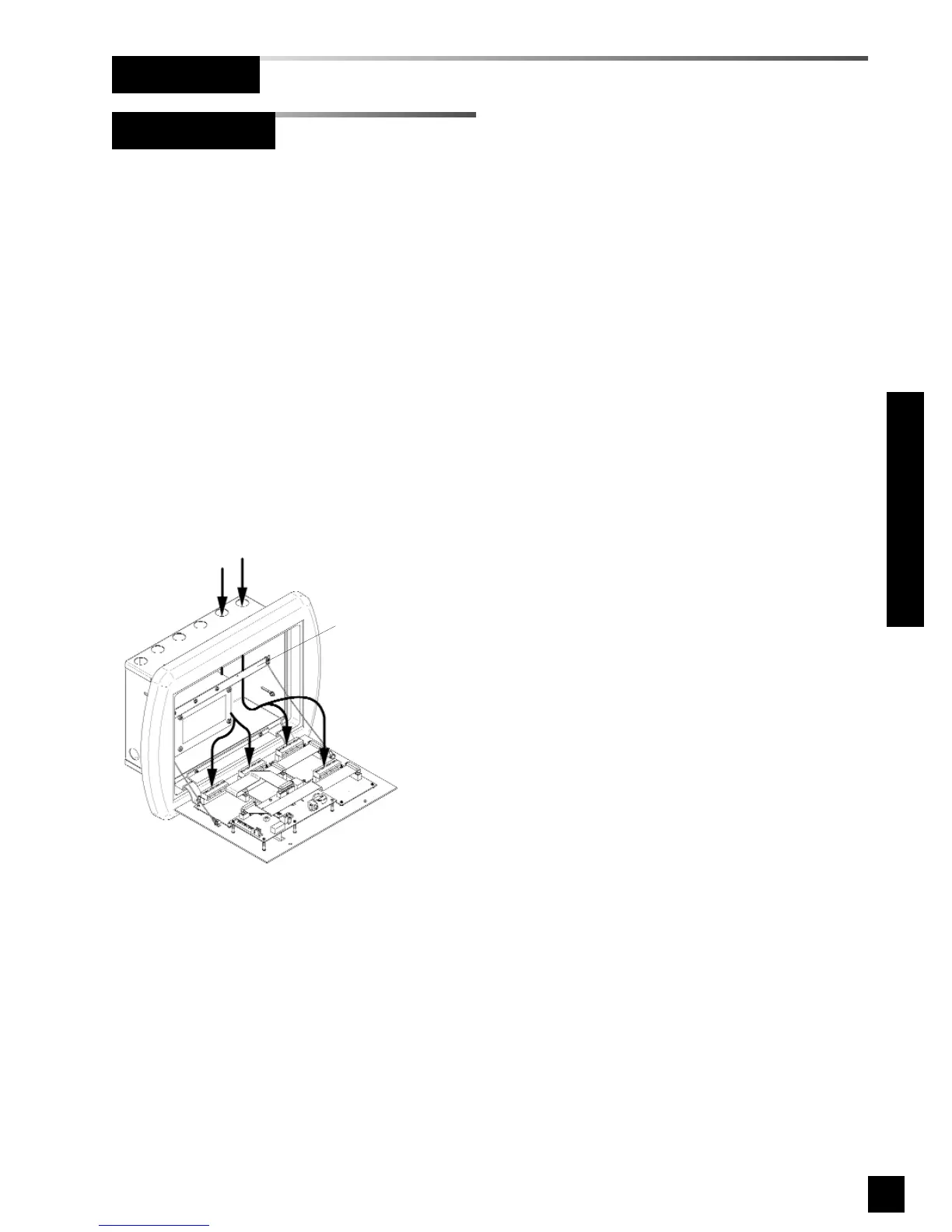
2. Route each pair of sensor wires as
shown in Figure 23 to appropriate
digital display module. Each digital
display module is labeled with the gas
type. Verify the appropriate remote
sensor wires are connected to correct
digital display module.
3. Connect positive sensor wires to
terminals 5 and 6 for each remote
sensor and digital display module.
Refer to Wiring Schematic 2
(Page 47).
Figure 23: Remote Sensor Wire Routing
Holes provided for
entrance of remote wiring
Route wires behind
metal brace
Remote Sensor
Wiring (Cont.)
Installation Procedures