34
6-847718-00 Rev. B00
Wiring (Cont.)
Multi-Signal Module Inputs
Installation Procedures
1. Identify each pair of field installed
source equipment signal wires inside
alarm panel back box assembly.
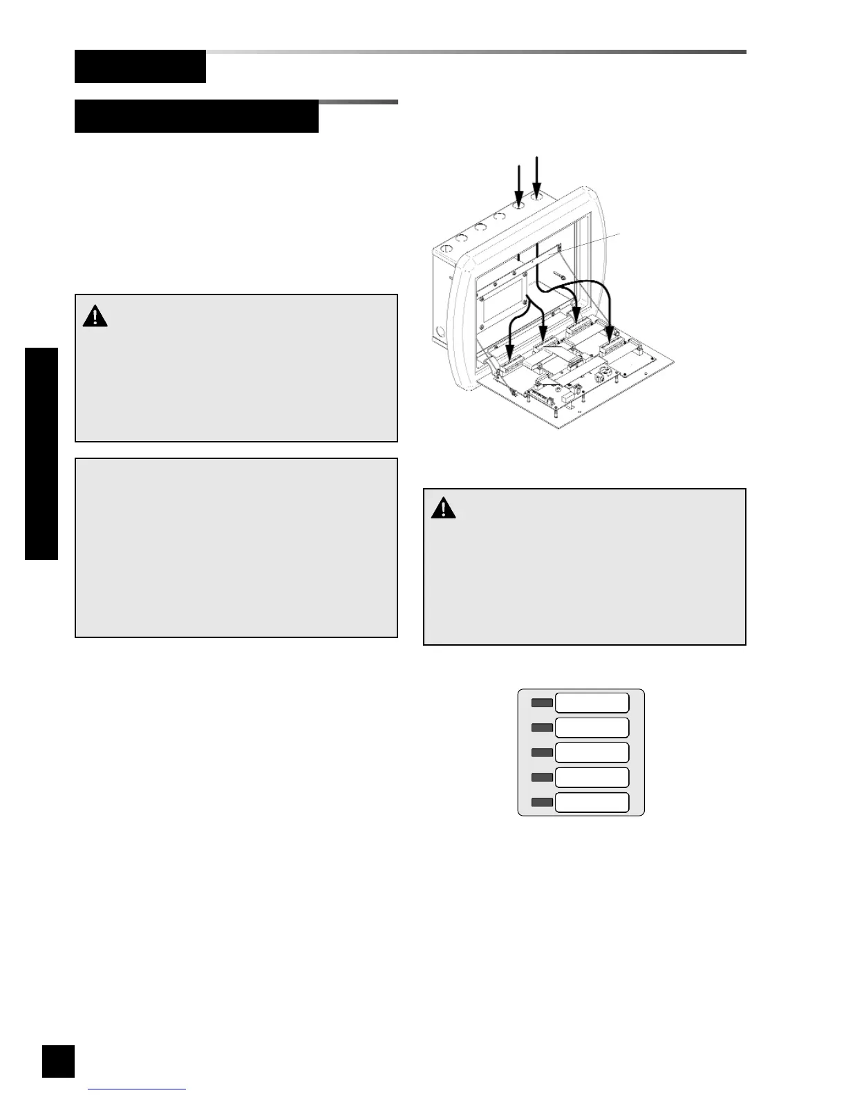
2. Route each pair of signal wires as
shown in Figure 26 to appropriate
multi-signal module.
3. Connect each pair of signal wires to
desired multi-signal module terminals.
The terminals are labeled “Signal 1”
through “Signal 5”. Refer to Wiring
Schematic 5 (Page 50).
Signal 1 corresponds to top row of
indicators on front panel of multi-signal
module. Signal 5 corresponds to
bottom row (Figure 27).
NOTE:
Each pair of terminals labeled on the multi-signal
module connector is labeled “+” and “COM”.
Ensure that when a source equipment dry contact
is wired to two master panels, the same side of
the dry contact is connected to the same terminal
at both panels. For example, if the source equip-
ment’s normally closed contact is wired to the “+”
of the first master panel, ensure it is also connect-
ed to the “+” terminal of the second master panel.
Holes provided for
entrance of remote wiring
Route wires behind
metal brace
Figure 27: Multi-Signal Module Signal Numbering
Signal 1
Signal 2
Signal 3
Signal 4
Signal 5
CAUTION:
Source equipment signal wires must be connect-
ed to normally-closed, dry contacts. No electrical
voltage can be present and contacts must be
closed during normal equipment operation. When
contacts open, an alarm condition will be activat-
ed.
Figure 26: Source Equipment Wire Routing
CAUTION:
Do not connect TotalAlert 2 master/combo alarm
to switch/relay contacts connected to any alarm
panels other than those listed below:
• TotalAlert 2
• MEGA2
• MEGA