48
6-847718-00 Rev. B00
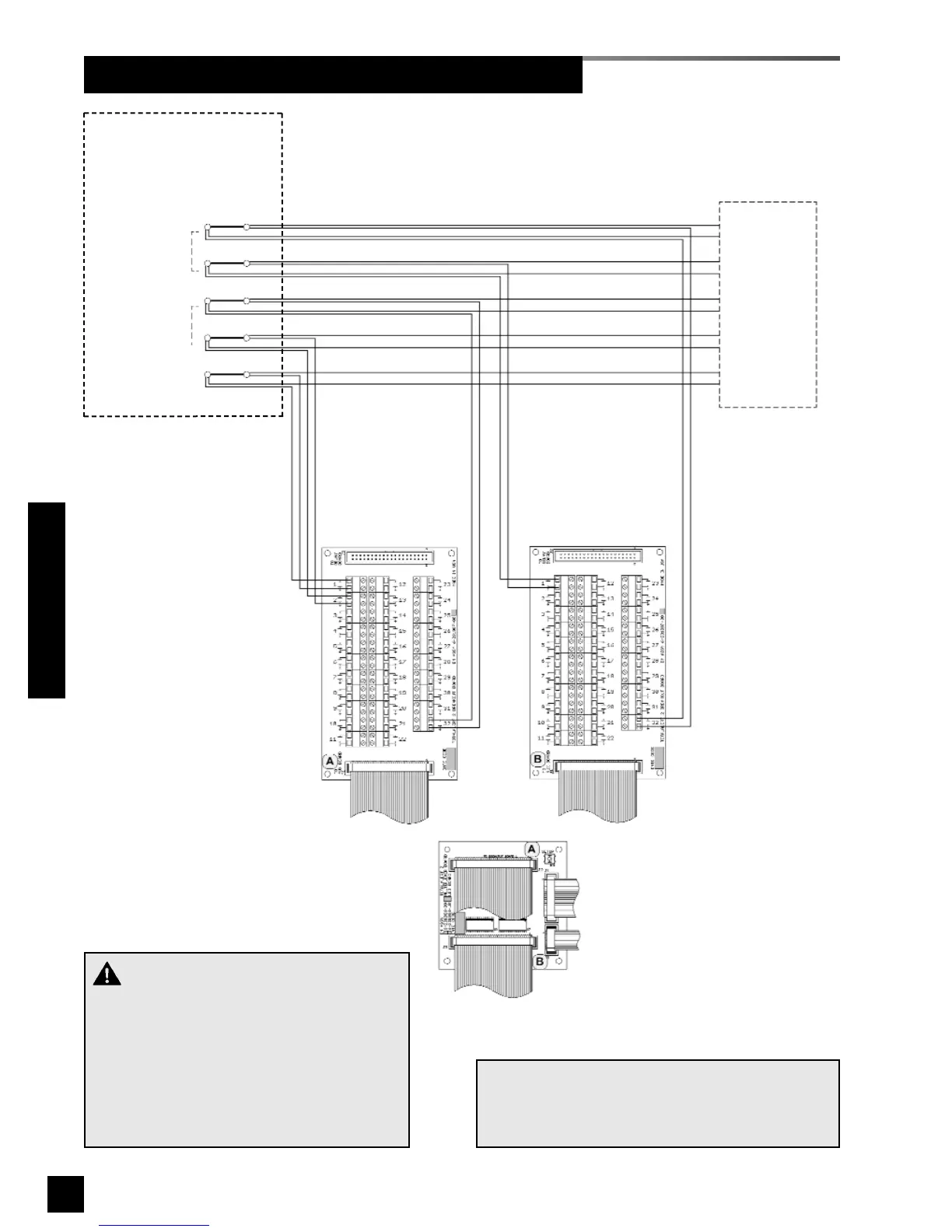
Wiring Schematic 3: Multiplexer / Breakout Boards
Wiring Schematics
20-wire ribbon cable
to modules
10-wire ribbon cable
to LED module
40-wire ribbon cable
to multiplexer module
connector A
40-wire ribbon cable
to multiplexer module
connector B
Multiplexer module
SIGNAL B32
SIGNAL B1
SIGNAL A32
SIGNAL A2
SIGNAL A1
Dry normally-closed
contacts at source
equipment or line
pressure switches
COM
+
COM
+
COM
+
COM
+
COM
+
NOTE:
Field wiring cable shields must be grounded at
only one end, inside alarm panel back box. Refer
to page 39 for details.
To additional
master alarm
panel(s)
Breakout
board A
Breakout
board B
CAUTION:
Do not connect TotalAlert 2 master/combo
alarm to switch/relay contacts connected to
any alarm panels other than those listed
below:
• TotalAlert 2
• MEGA2
• MEGA