Two additional levels of “advanced” set-up
features are available. The first level is
used to adjust basic communication related
parameters. The second level is used to
adjust alarm repeat time and display
intensity.
Setting Communication Parameters:
A network address uniquely identifies each
alarm module in the alarm panel. Address
range is 0 to 255.
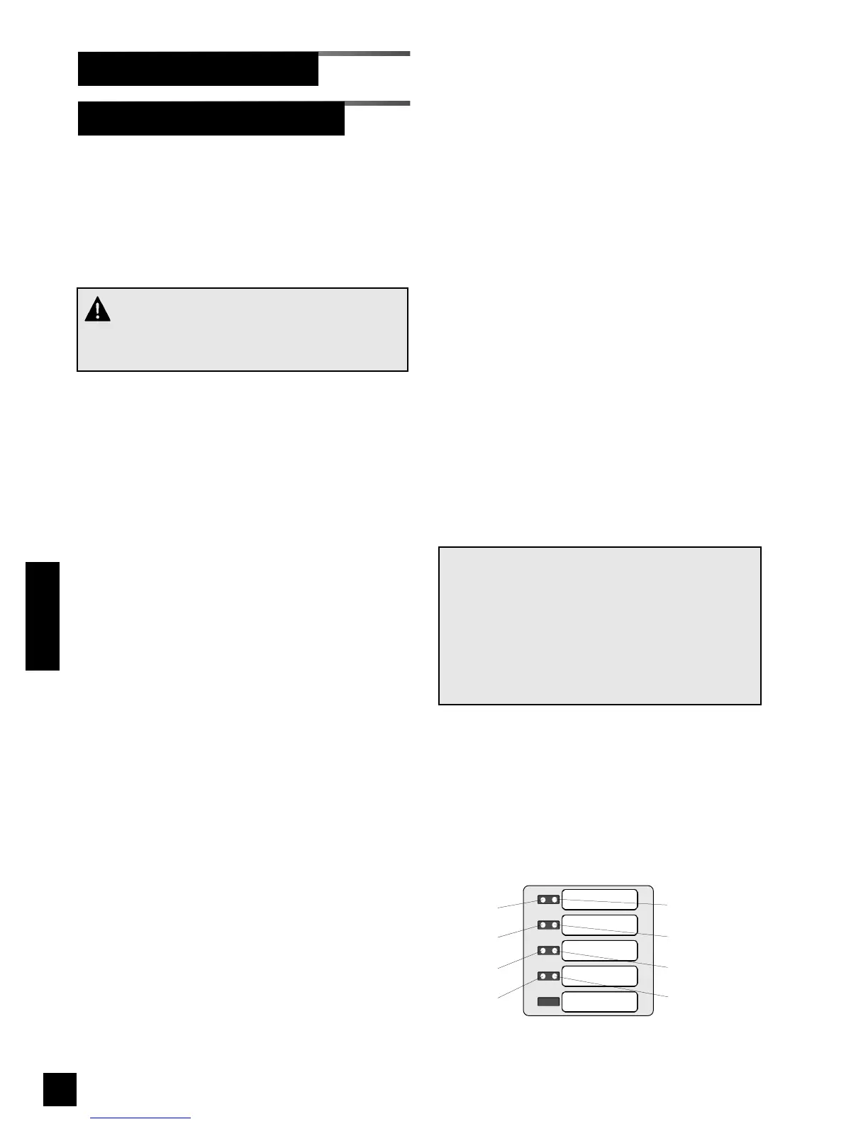
Network address is shown as a binary
number on specific red and green front
panel LEDs. A numeric value is assigned
to each LED (Figure 50)
For example, if LEDs for bits 1 and 2 were
illuminated, network address would be 6 (2
+ 4 = 6).
1. Press and HOLD set-up button.
Audible alarm will chirp when set-up
button is first pushed and again two
seconds later. Release button after
second audible alarm chirp.
2. Multi-signal alarm module front panel
LEDs will show current network
address. If no LEDs are illuminated,
address is 0.
2. Using either ! or " buttons, select
desired network address between 0
and 255.
3. Press and release TEST button on front
of alarm panel. Front panel LEDs (Bit 0
and Bit 4) will show current
communication baud rate. If only Bit 4
LED is illuminated, baud rate is 4800.
If BOTH Bit 0 and Bit 4 LEDs are
illuminated, baud rate is 9600.
Baud rate must be set to 9600 for
TotalAlert 2 alarm panels.
4. Using either ! or " buttons, select
desired baud rate (4800 or 9600).
5 Press and release TEST button on front
of alarm panel. Front panel LEDs (Bit 1
and Bit 5) will show current
communication data format. If only Bit
5 LED is illuminated, data format is 8-
bit word length (factory setting). If
BOTH Bit 1 and Bit 5 LEDs are
illuminated, data format is 16-bit word
length.
6. Using either ! or " buttons, select
desired data format (8-bit or 16-bit).
7. Press and release TEST button to save
changes. LEDs will sweep from top to
bottom to indicate end of set-up
sequence has been reached.
8. Multi-signal module will return to
monitoring mode.
NOTE:
If module is idle for more than one minute during
set-up procedure, module will chirp three times,
return to monitoring mode and will default to pre-
vious settings. No changes to settings will be
saved.
Set-up must be completed in order for changes
to be saved.
70
6-847718-00 Rev. B00
Multi-Signal Module-Advanced
Set-Up Procedures (Cont.)
Operation
SIGNAL 1
SIGNAL 2
SIGNAL 3
SIGNAL 4
SIGNAL 5
Bit 4 (16)
Bit 0 (1)
Bit 1 (2)
Bit 2 (4)
Bit 3 (8)
Bit 5 (32)
Bit 6 (64)
Bit 7 (128)
Figure 50: Binary data represented by LEDs
Red LEDs
Green LEDs
CAUTION:
Communication parameters are factory set and
should not be changed.