52
6-847718-00 Rev. B00
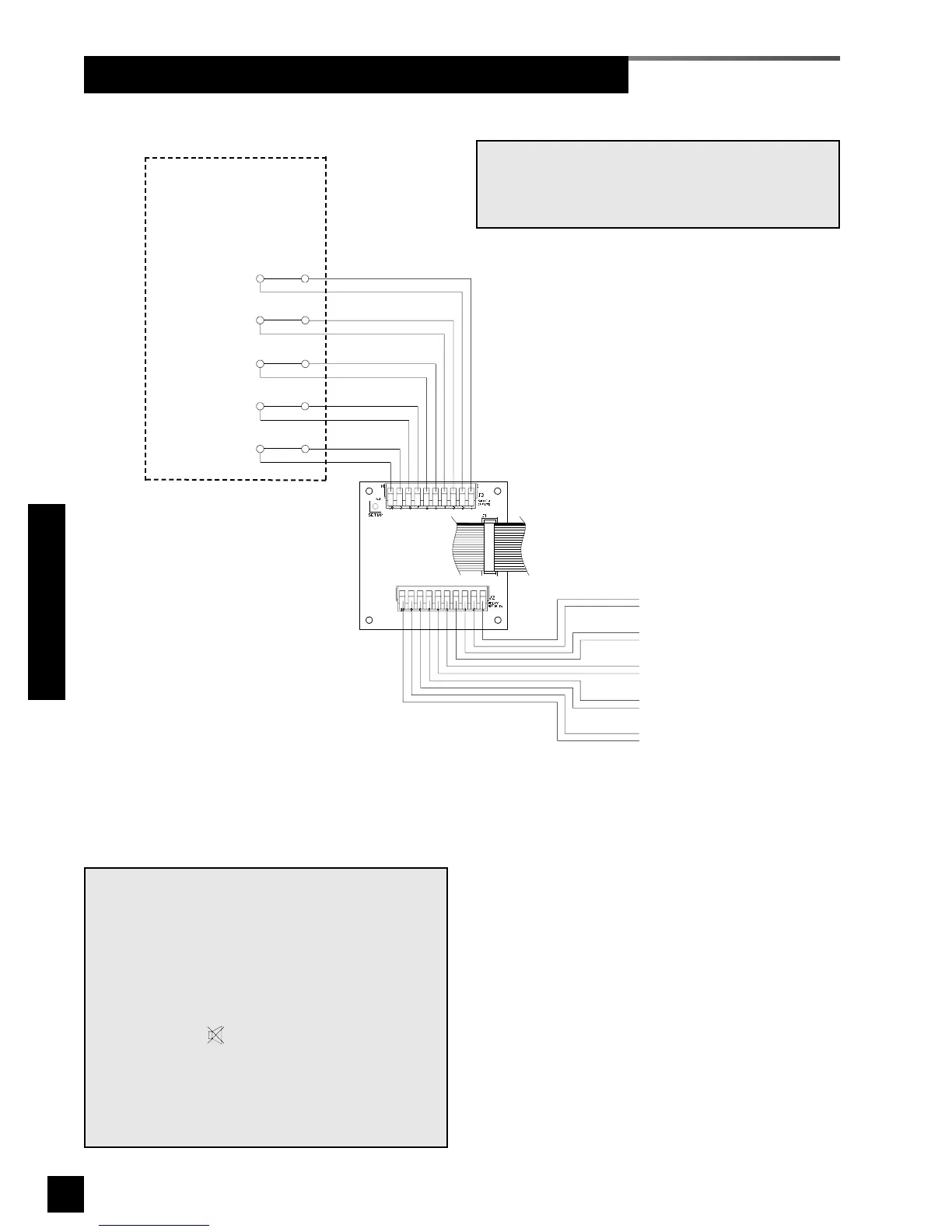
Wiring Schematic 7: Multi-Signal Module Relay Outputs
SIGNAL 1
SIGNAL 2
SIGNAL 3
SIGNAL 4
SIGNAL 5
Dry normally-closed
contacts at source
equipment or line
pressure switches
COM
+
COM
+
COM
+
COM
+
COM
+
Multi-Signal Module
with relays
20 wire
ribbon cable
to adjacent
module
SIGNAL 1 - pins 1 & 2
SIGNAL 2 - pins 3 & 4
SIGNAL 3 - pins 5 & 6
SIGNAL 4 - pins 7 & 8
SIGNAL 5 - pins 9 & 10
Dry normally-closed
output relay contacts
NOTE:
Output relay contacts are dry normally closed
type.
Contacts open upon designated alarm activation.
Contacts remain open until alarm condition is cor-
rected.
Pressing MUTE on Annunciator Module WILL
deactivate relay until audible alarm is again reacti-
vated.
Relay contact ratings are 2 A @ 30 VDC/0.5 A @ 125
VAC
.
NOTE:
Field wiring cable shields must be grounded at
only one end, inside alarm panel back box. Refer
to page 39 for details.
Wiring Schematics
 Loading...