932 655 638 2014-02-14| Beissbarth GmbH
30 | MT 788 | Commissioningen
4. Commissioning
4.1 Unpacking
1. Remove the steel bands and fasteners.
2. Carefully lift off the packaging.
3. Remove the wheel guard, accessories and packaging
material from the packaging unit.
i Check that the MT 788 and the accessories are in
proper working order and that there are no visible
signs of component damage. In case of doubt, do
not start up the unit and consult customer service.
i Remove the accessories and packaging material from
the packaging unit.
4.3 Set-up
1. Slacken off the bolts with which the MT 788 is at-
tached to the pallet.
WARNING – Defective or incorrectly at-
tached lifting straps!
Risk of injury due to MT 788 falling down.
¶ Check lifting straps for physical damage
before attaching.
¶ Tighten lifting straps uniformly.
¶ Lift MT 788 carefully.
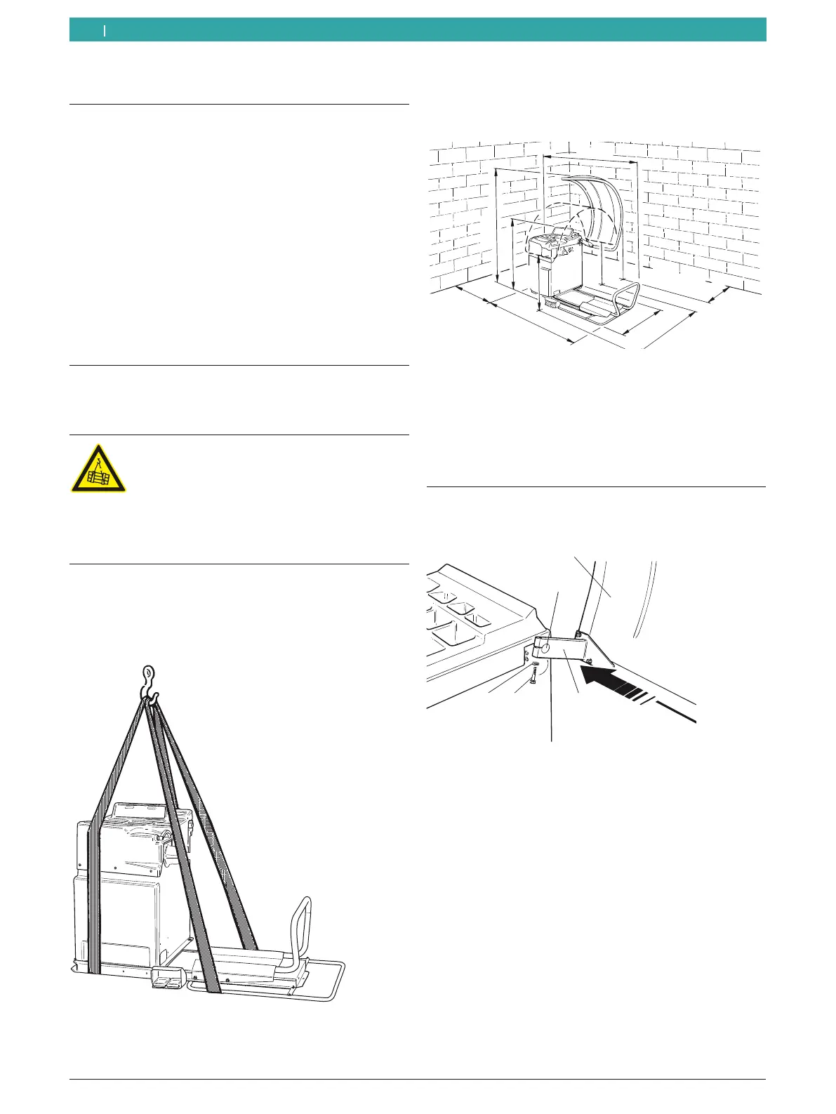
2. Attach lifting straps of equal length and with an ade-
quate loadbearing capacity (at least 100 kg)
as shown.
651016-06 _Mi
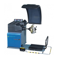
3. Use a crane to lift the MT 788. Set up the unit in
the intended area, paying attention to the specified
minimum distances.
651016-02 _Mi
2000
1950
1000
1000
500
1830
900
1350
500
i For safe and ergonomical operation, it is advisable to
set up the MT 788 at a distance of 500 mm from the
nearest wall.
4. Fasten the MT 788 to the floor at a minimum of 3
points.
4.2 Fitting the wheel guard
1. Slide the wheel guard onto the mounting pins.
651016-07 _Sr
1
2
3
4
5
Fig. 2: Attaching the wheel guard to the MT 788
1 Wheel guard
2 Hexagon socket head bolt
3 Washer
4 Nut
5 Mounting pins
.
2. Insert the hexagon socket head bolt and washer
through the mounting flange hole and tighten slightly.
3. Setting angle of protective cover: With the wheel gu-
ard open, the front section of the wheel guard must
be roughly 1900 mm above the floor.
4. Finish-tighten the hexagon socket head bolt.
! After tightening, check that the front section of the
wheel guard is roughly 1000 mm above the floor with
the guard closed.
 Loading...