47
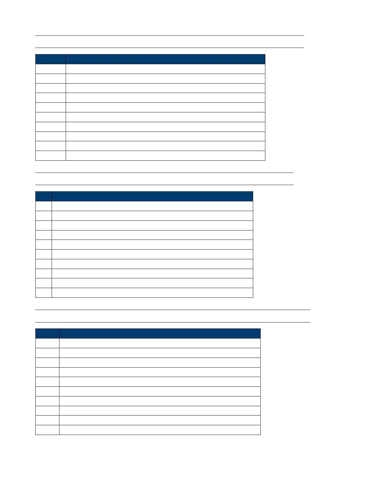
12.12 Set/Read CV transient voltage and timer parameter. (34H/35H)
Byte Description
1 AAh
2 Address (0-31, 0XFF)
3 Command 34H/35H
4-7. Setting value of voltage A (Low byte to High byte order)
8-9th byte. Time value of timer A (Low byte to High byte order) (1represent 0.1mS)
10-13 Setting value of voltage B (Low byte to High byte order)
14-15 Time value of timer B (Low byte to High byte order) (1represent 0.1mS)
16 Transient operation mode (0 is CONTINUES, 1 is PULSE, 2 is TOGGLED)
17-25 Reserved
26 Checksum
12.13 Set/Read CW transient watt and timer paramete. (36H/37H)
Byte Description
1 AAh
2 Address (0-31, 0XFF)
3 Command 36H/37H
4-7 Setting value of power A (Low byte to High byte order)
8-9 Time value of timer A (Low byte to High byte order) (1 represent 0.1mS)
10-13 Setting value of power B (Low byte to High byte order)
14-15 Time value of timer B (Low byte to High byte order) (1 represent 0.1mS)
16 Transition operation mode (0 is CONTINUES, 1 is PULSE, 2 is TOGGLED)
17-25 Reserved
26 Checksum
12.14 Set/Read CR transient resistance and timer paramete. (38H/39H)
Byte Description
1 AAh
2 Address (0-31, 0XFF)
3 Command 38H/39H
4-7 Setting value of resistance A (Low byte to High byte order)
8-9. Time value of timer A (Low byte to High byte order) (1 represents 0.1mS)
10-13 Setting value of resistance B (Low byte to High byte order)
14-15 Time value of timer B (Low byte to High byte order) (1 represents 0.1mS)
16 Transition operation mode (0 is CONTINUES, 1 is PULSE, 2 is TOGGLED)
17 to 25 Reserved
26 Checksum

 Loading...


