Access Easy Controller Secure/Communication Card | en 121
Bosch Security Systems Hardware Manual Ver 2.0.0 | 2006.07
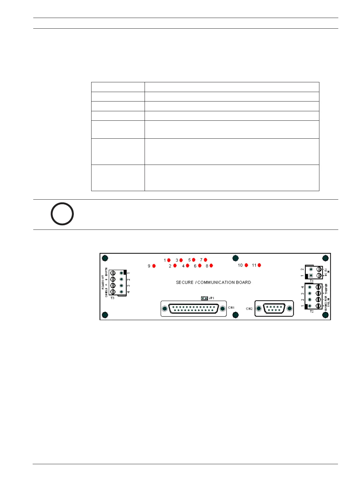
16.2.1 LED Indicators
There are 11 Light Emitting Diodes (LEDs) on the CPU Card. The status of these LED indica-
tors allows for quick diagnostics purposes. Their indicating status is described below: -
LED 1 Indicates I/O process is running.
LED 2 Indicates that reader process is running.
LED 3 Indicates serial communication process is running.
LED 7 Indicates total communication failure for all extension boards.
LED 8 Indicates the ARP enabled for IP configuration/IP has been reset
to default address.
LED 9 Indicates the CPU is accessing the SAM chip on board the
Secure/Communication Card. Each time the CPU access the
SAM, this LED will blink once.
LED 10 & 11 These two LED indicates the communication status between the
Convertor Card and the Secure/Communication Card. It will be
flickering at all time.
i
NOTICE!
After successful startup, LED 1,2 & 3 will runs in a rotating sequence.