Access Easy Controller The CPU Card | en 89
Bosch Security Systems Hardware Manual Ver 2.0.0 | 2006.07
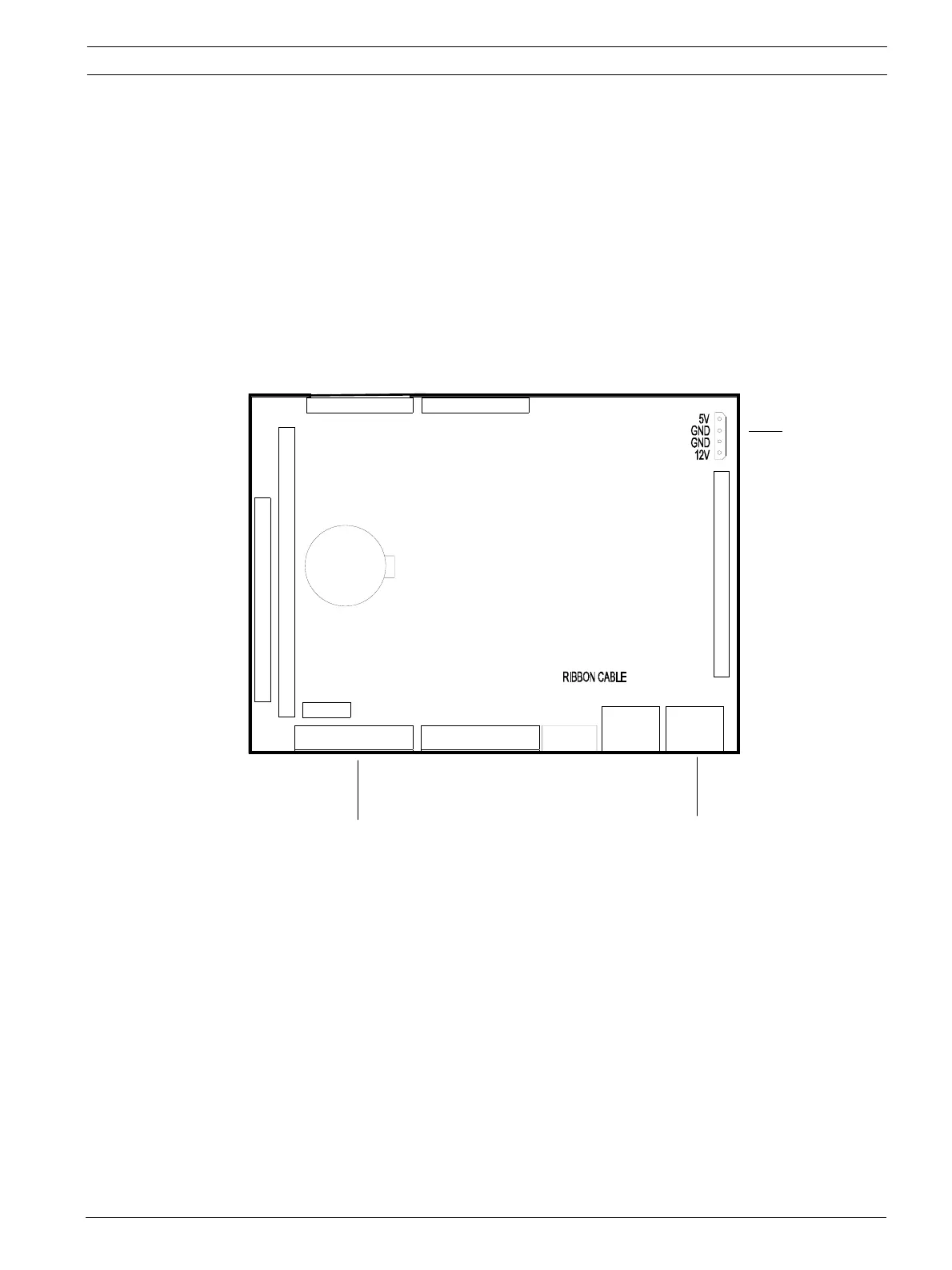
14.1 Component Layout of the CPU Card
Refer to the following layout drawings, which show the major physical components on the
CPU Card. A brief description is provided on some of the major components.
We have 2 different types for the CPU Card, hence the layout of each type will be slightly dif-
ferent. The following drawings will show each type and the location of the relevant compo-
nents.
CPU board
LAN LAN
COM 1
VGA
PORT 2 PORT 1
PIN 1
CN11
(P/N: AEC MOD CPU)
CPU BOARD
PIN 1
CN1
PS2
12VDC & 5VDC
Connector
Enternet Lan Port
Serial Com Port for Modem