Access Easy Controller 4-Reader Boards and 8 Input/8 Output Boards | en 99
Bosch Security Systems Hardware Manual Ver 2.0.0 | 2006.07
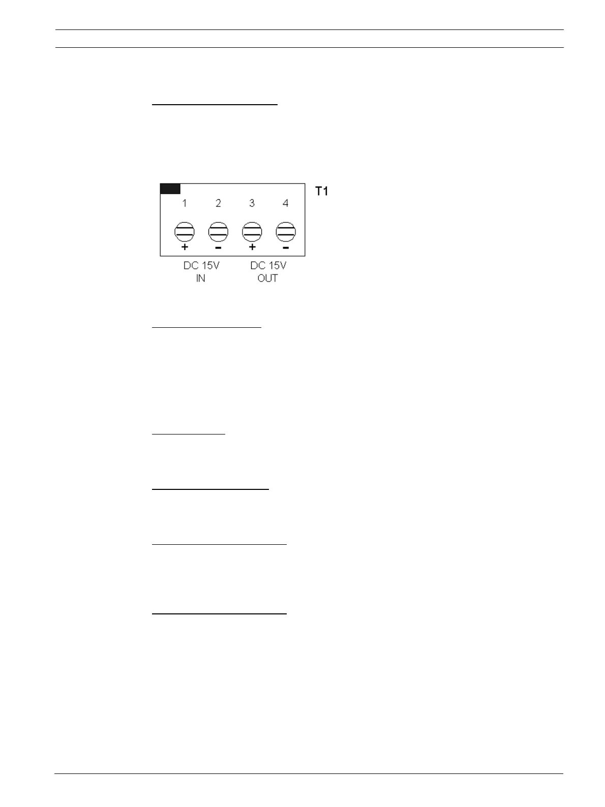
15.2.3 15VDC Input Termination
Reference: Terminal Strip T1
Terminals T1-1 and T1-2 are used to provide 15 Volt DC power to the 4-reader board. Power is
supplied from the output terminals on the Power Supply card. Terminals T2-3 and T2-4 are
available to provide 15 VDC power to other cards. The diagram below shows the configura-
tion of the terminal strip.
15.2.4 IDE Connectors
Reference: CN1 and CN2
These are a pair of parallel-connected 40-pin IDE connectors. They are used as the data link
between the 4-reader board and other 4-reader board and/or 8input/8output card board. The
connector is used to extend the IDE bus to the next card.
15.2.5 LED Indicators
Reference: LED9
This LED indicates +15 VDC power is present.
Reference: LED 1 to LED 8
LEDs 1 to 8 light whenever the associated relay is activated.
Reference:
LED 11 and LED 13
These LEDs should alternately blink in normal operation. This indicates normal communica-
tion between the 4-reader board and the CPU card.
Reference:
LED 10 and LED 12
These LEDs will blink once each time card is presented to a reader.
LED10 will blink when a card is presented to either reader 1 or 2.
LED12 will blink when a card is presented to either reader 3 or 4.
Jumper Setting