98 en | 4-Reader Boards and 8 Input/8 Output Boards Access Easy Controller
Ver 2.0.0 | 2006.07 Hardware Manual Bosch Security Systems
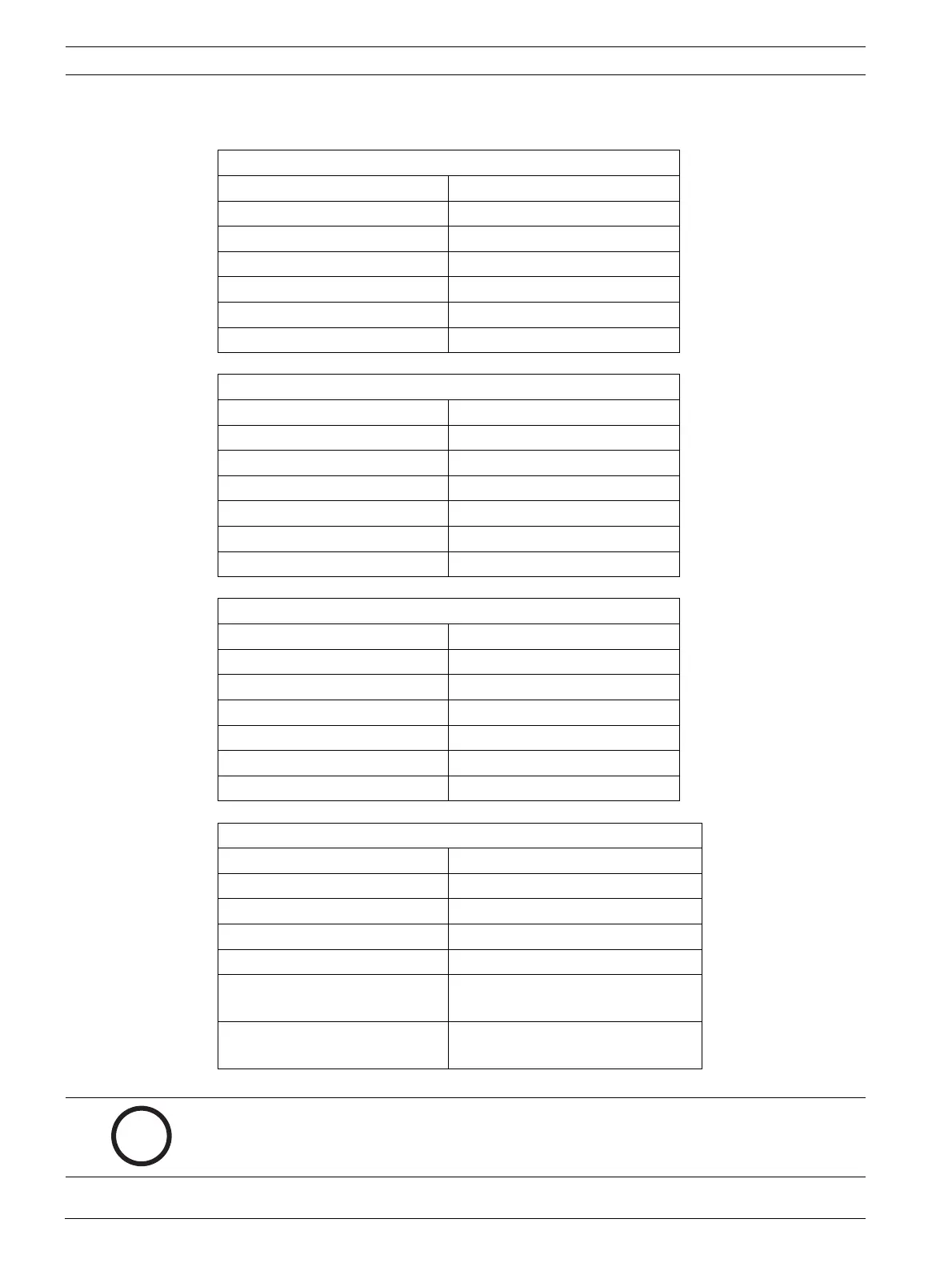
Connector T2 (top connector)
Pin# Function
1 Reader #1 (common)
2 Reader #2 (Normally closed)
3 Reader #1 (normally open)
4 Reader #2 (common)
5 Reader #2 (normally closed)
6 Reader #2 (normally open)
Connector T3 (second connector from top)
Pin# Function
1 Reader #3 (common)
2 Reader #3 (Normally closed)
3 Reader #3 (normally open)
4 Reader #4 (common)
5 Reader #4 (normally closed)
6 Reader #4 (normally open)
Connector T4 (third connector from top)
Pin# Function
1 Spare (common)
2 Spare (Normally closed)
3 Spare (normally open)
4 Spare (common)
5 Spare (normally closed)
6 Spare (normally open)
Connector T5 (bottom connector)
Pin# Function
1 Spare (common)
2 Spare (Normally closed)
3 Spare (normally open)
4 Common Alarm Output (common)
5 Common Alarm Output (normally
closed)
6 Common Alarm Output (normally
open)
i
NOTICE!
The common alarm output relay only exists on 4-reader board 1. On cards 2, 3 and 4 this relay
is an additional spare.