G
B
B
A
D
E F
C H
194
6.8 Installing Drive Unit (BDU310/350)
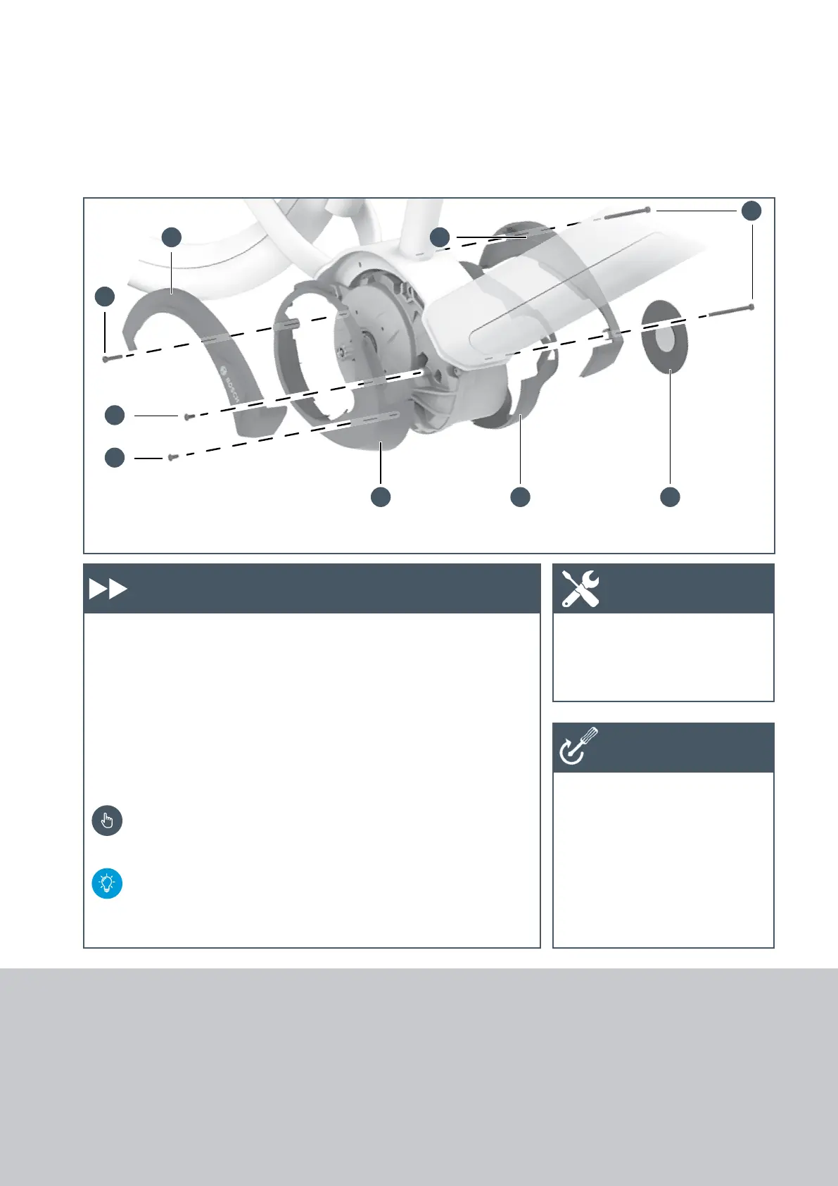
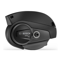
Installing the Active Line (BDU350) design cover
1. Place the right-side lower design
cover (A) on the drive unit and
screw onto the housing using two
M4 x 10 self-tapping screws (B).
2. Place the left-side lower design
cover (C) on the drive unit and
screw the two design covers
together using M4 x 20 (D)
screws.
Pay attention that both parts
engage into each other cor-
rectly.
If necessary, unscrew them
slightly and then screw them
in again using a torque of
1 Nm.
3. Place on the right-side upper
design cover (E) and clip into
the lower design cover (A).
4. Place on the left-side upper
design cover (F)
and screw on
using two screws (G) (M4 x
55).
5. If necessary, glue on the logo
cover (H).
– Gluing surface clean/free of
grease
– Pay attention to the installa-
tion position: Lettering posi-
tioned horizontally
– Firmly press the cover on the
gluing surface for 10 seconds.
X Torx wrench T20
X Torque wrench
X Design cover: 1 Nm
Work steps Tool
Tightening
torques
6.8 Installing Drive Unit
(BDU310/350)





 To Next Page