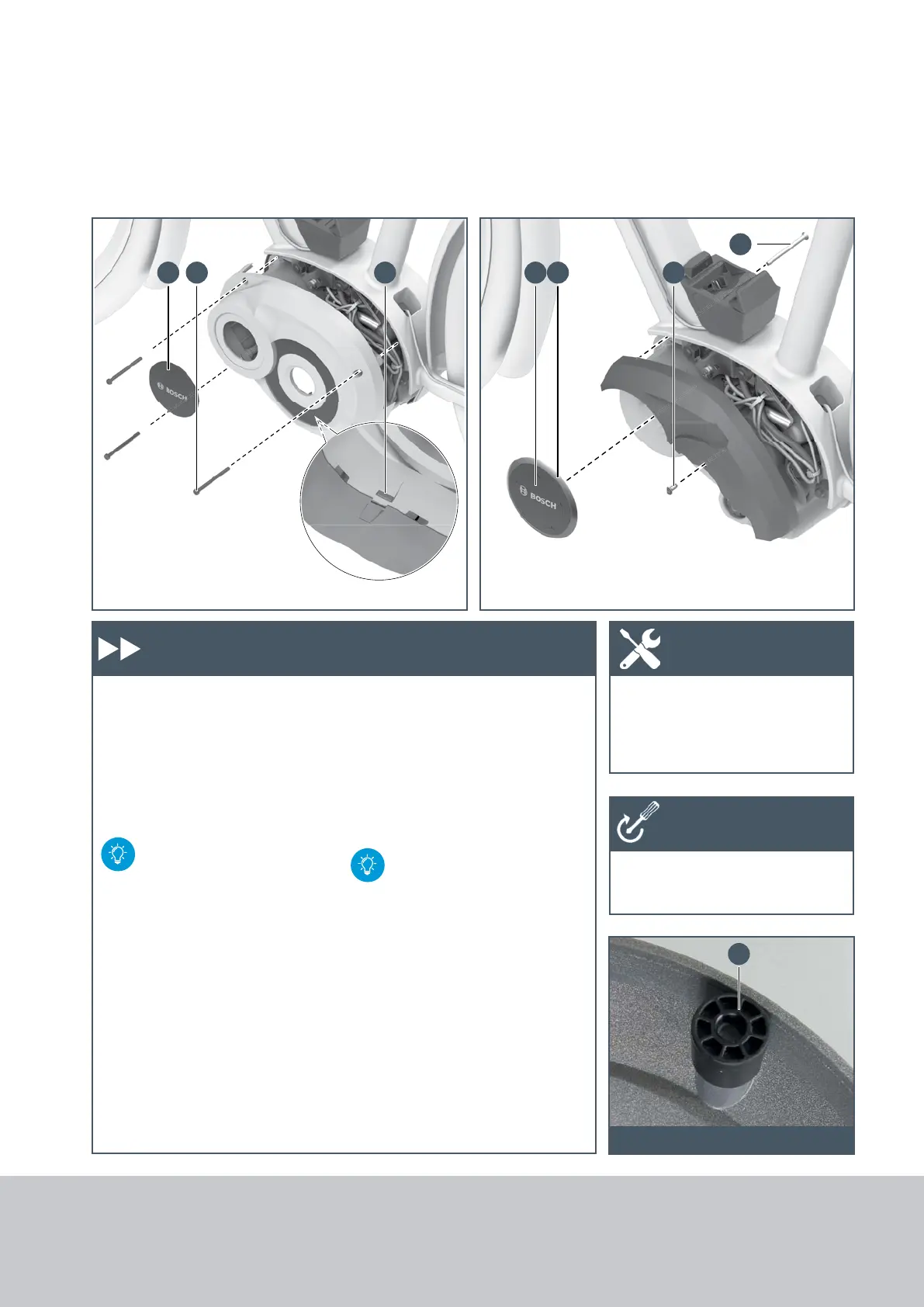
G G F D
C
B A
E
204
6.10 Installing Drive Unit (BDU250C/255C)
Installing the design cover
1. Place both design covers on the
drive unit and position them
without applying pressure.
Allow the latches (A) to engage.
2. Screw in the three plastic
screws (B) (M4 x 55).
Make sure the screws are
seated correctly in the
threads. If necessary,
unscrew them slightly and
then screw them in again.
X When using the short mounting
plate, a spacer sleeve (C) is
required for the installation of
the design cover. (is delivered
pre-assembled; also as a spare
part Order number:
1.270.015.109)
Cable guard for
Performance Line CX
X Fasten cable guard with two
screws (D, E) on the drive unit.
Gluing on the logo cover
1. The gluing surface must be
grease free (cleaned).
Performance Line CX: An
additional ring (F) is
required for installation of
logo cover (included in logo
cover scope of delivery).
2. Glue on the logo cover (G).
3. Pay attention to the installation
position: The BOSCH lettering
must be positioned horizon-
tally.
4. Firmly press the cover on the
gluing surface for 10 seconds.
X Torx wrench T20
X Torque wrench
X Design cover: 1 Nm
X Cable guard: 1 Nm
Work steps Tool
Tightening
torques
Spacer sleeve in the design cover
6.10 Installing Drive Unit
(BDU250C/255C)







 To Next Page