1 689 975 233 2018-05-08| Robert Bosch GmbH
Checklist for normal operation | EPS 708 | 17 en
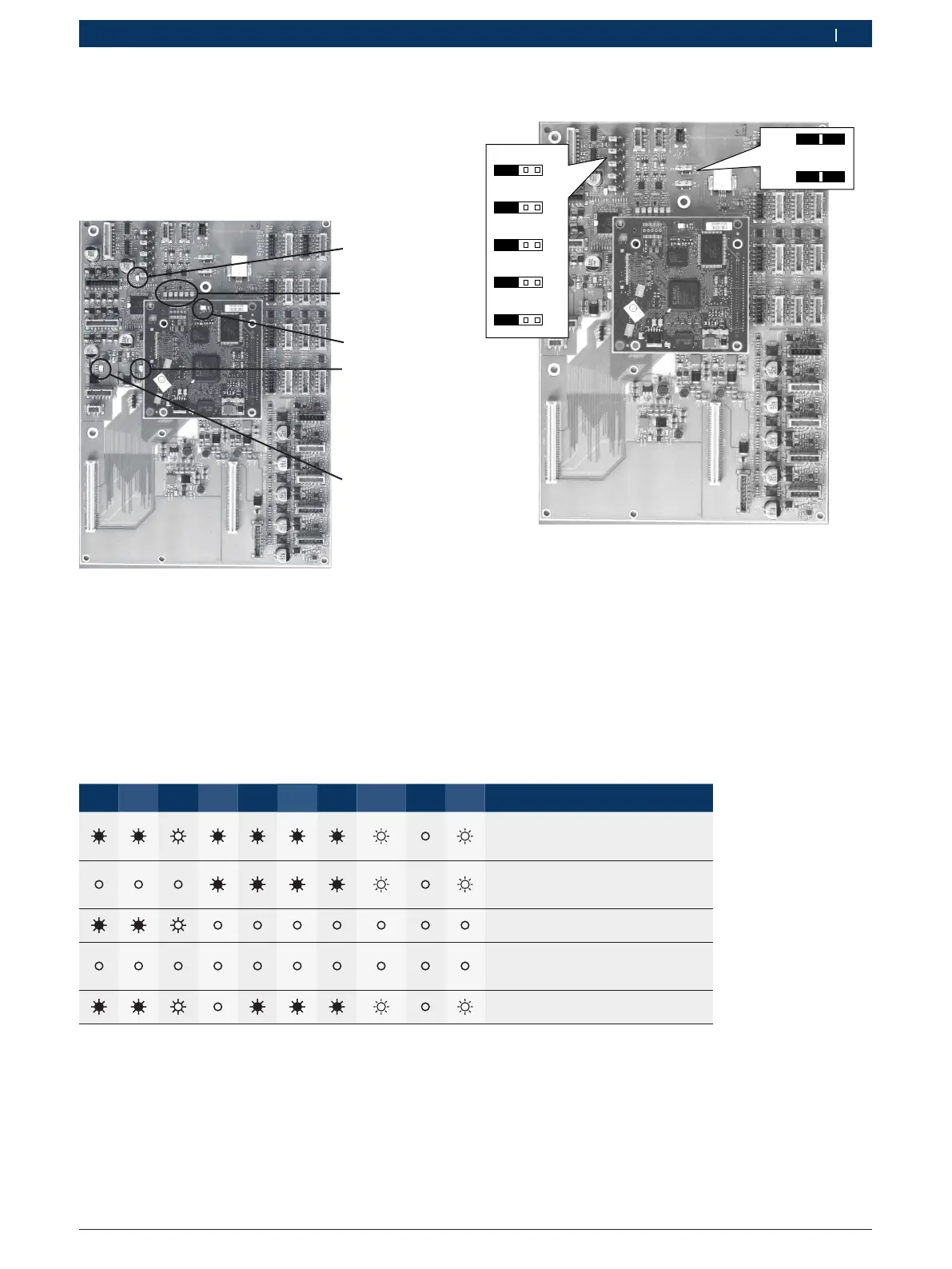
5.3.5 PCB (A14)
i Circuit board A14 is included in the scope of delive-
ry of retrofit kit CP4 (1687010390) and replaces
circuit board A6 when making the conversion.
458863-60_Pal
V30 V70 V96
V72 V74 V82
V1
V21
V22
V23
Fig. 24: Circuit board 1 688 400 537
V21 15V external voltage supply
V22 5V internal voltage supply
V23 No function
V30 5V internal voltage supply of pressure sensors
V70 6.5V internal voltage supply
V96 13.5V internal voltage supply
V72 3.3V internal voltage supply
V74 USB communication status (LED flickers)
V82 No function
V1 Firmware status LPC800
V21 V22 V23 V30 V70 V96 V72 V74
1)
V82 V1 Status
voltage supply and processor in
good working order. No faults oc-
curred
Emergency stop active or 15 V po-
wer supply 24 V voltage supply via
plug X320
2)
faulty
24 V voltage supply via plug X1
2)
faul-
ty
24 V voltage supply via plug X1
2)
and
15V voltage supply via plug X320
2)
faulty
Short circuit 5 V voltage supply for
pressure sensor B48 or B49
1)
LED flashes during active USB communication. The LED is off in
the absence of USB communication.
2)
See connection diagram 1 689 927 302 in the appendix
Jumper setting for circuit board (A14)
X31X34X33X32X35
X49
X2
458797-39_Pal
Fig. 25: Jumper settings