Page 1045349D © 2002 Radionics
D6412/D4412 Installation Guide
D6412/D4412
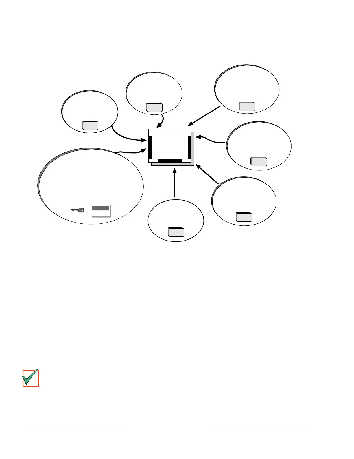
2.0 Overview
DX2010
Point Expansion Module
DX3010
Octo-Output Module
Use Command Centers and/or keyswitches to
arm the panel by area. Each area can have its
own account number or areas can be grouped
together with a common account number.
Points of protection are assigned to areas.
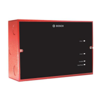
Control/
Communicator
8 On-Board
Sensor Loops
4 On-Board
Outputs
D8132 modules provide
additional power for command
centers and other powered
devices.
DX4010
Serial Interface Module
(for connection of serial printer
or other RS-232 device)
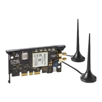
RF3224 Premises
RF Receiver
(up to 4 RF keypads
and 32 keyfobs)
DX3020 Module
Provides control for
X-10 modules.
Figure 1: System Configuration
2.1 Specifications
2.1.1 Voltage Input
Primary
18 VAC 22 VA class 2 plug-in transformer CX4010 (D1825)
Secondary
12 VDC, 7 Ah sealed lead acid rechargeable battery or 12 VDC, 18 Ah sealed lead acid rechargeable battery.
2.1.2 Current Requirements
Panel – 100 mA
See Appendix A, Approved Applications Compliance Guide, for the current requirements of other system
components.
2.1.3 Power Outputs
Continuous Power
Up to 600 mA maximum at 11.5 VDC to 12.4 VDC (continuous supply) total for all devices and outputs for non
UL applications.
IMPORTANT
Up to 400 mA at 11.5 VDC to 12.4 VDC for UL listed burglary applications, 120 mA for Fire and
Combined Burglary/Fire (continuous supply) total for all devices and outputs.
Alarm Power
400 mA for Fire and combined Fire/Burglary; 1500 mA for UL Burglary; 1850 mA for other (not investigated by
UL). Applies to all four outputs combined. See the Outputs section of the D6412/D4412 Program Entry Guide
(P/N: 45351).
Overview