Page 2245349D © 2002 Radionics
D6412/D4412 Installation Guide
D6412/D4412
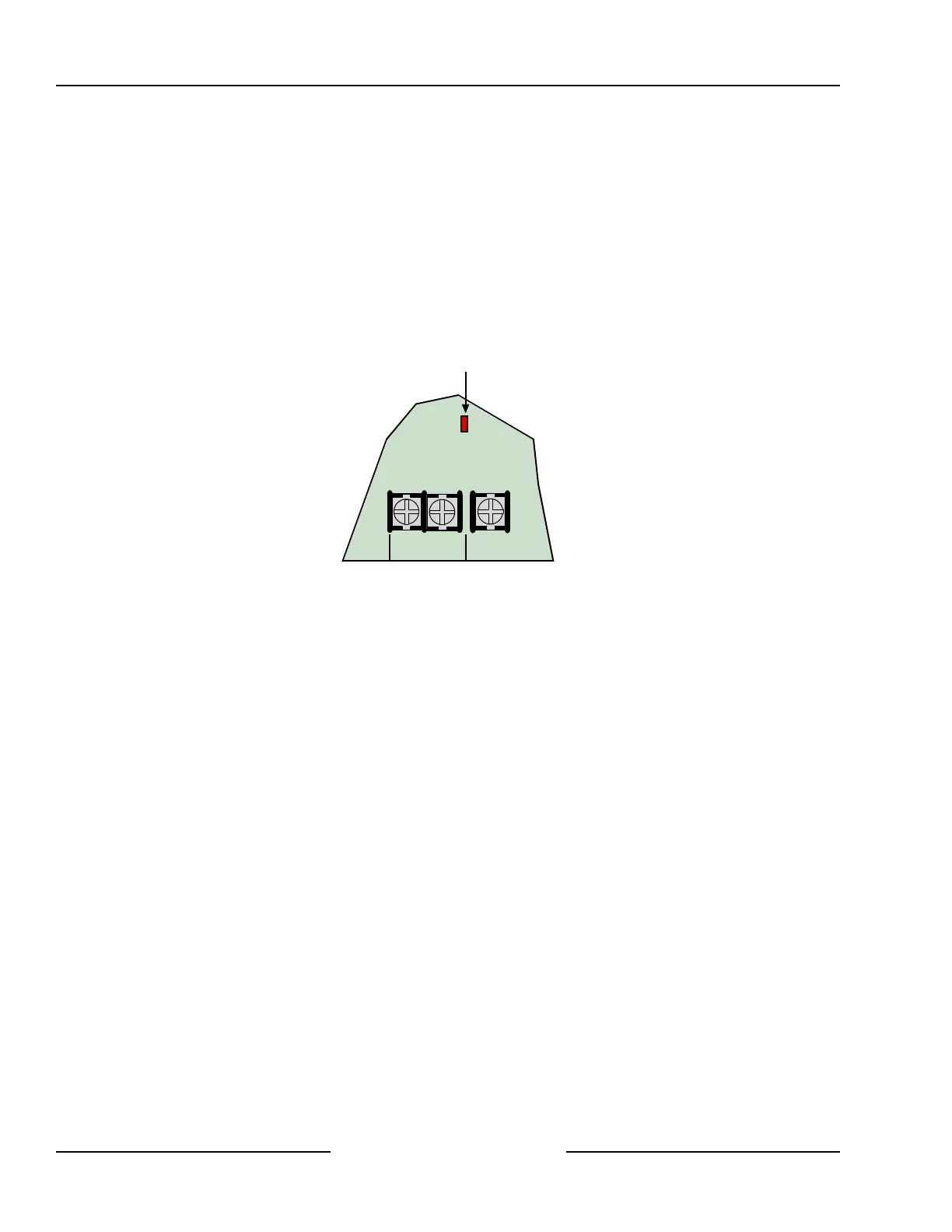
4.2.7 System Status LED
The System Status LED shows system status, including power supply status as described below.
Figure 4 shows the location of the LED on the panel.
System Normal on for 50 ms, off for 1 sec.
Battery Missing off for 200 ms, on for 1 sec.
AC Missing off for 200 ms, on for 200 ms, off for 200 ms, on for 1 sec.
Phone Ringing flickers for 1 sec. as each ring is detected.
Phone Line Seized (panel using phone line) on solid.
Shut Down (system voltage below 10.2 VDC) off 200 ms, on for 200 ms, off 200 ms, on for 200 ms, off 200
ms, on for 1 sec.
L-2Com L-3
System Status LED
Figure 4: System Status LED
4.3 External Power Supply
The external power supply (not supplied) is not intended to provide power to indicating devices for burglary and
fire applications.
• Burglary Applications: use a UL603 Listed burglar alarm power supply with an operating voltage range of
11.8 to 12.4 VDC for Bank Safe/Vault applications (72 hours of standby battery required).
• Fire Applications: use a UL1481 Listed power supply operating voltage range of 11.8 to 12.4 VDC for fire
applications.
5.0 Power Outputs
5.1 Circuit Protection
Three self-resetting thermal circuit breakers protect the panel from short circuits on both the continuous and
programmable power outputs. If the panel is programmed for power supervision and a short is sustained on one
of the power outputs, the panel transmits a BATTERY LOW or BATTERY MISSING report.
One breaker protects Auxiliary Power and the Installer’s Keypad Connector. A short on one disrupts the power
to the other.
One breaker protects the Alarm Power Output, (Alrm + Terminal) and one breaker protects the battery.
5.2 Available Power
5.2.1 Auxiliary Power
Use the auxiliary power terminals to power devices requiring continuous power. See Sections 14.0 and 15.0 for
the location and description of these terminals.
5.2.2 Installer’s Keypad Connector
Use this connector to connect an installer’s keypad to the panel for programming and diagnostics.
Power Outputs