Page 41© 2002 Radionics
D6412/D4412 Installation Guide
45349D
D6412/D4412
9.0 On-Board Outputs
The panel supports up to four on-board programmable outputs (PO 1 to PO 4).
Programmable Output 2 (PO 2) can be configured as a supervised siren driver. See Global Output Configuration
in the D6412/D4412 Program Entry Guide (P/N: 45351) for programming instructions. When programmed as a
siren driver, PO 2 draws power from the Alrm + terminal. When connected to a 4 Ω horn/speaker, PO 2 draws
380 mA of power. When connected to an 8 Ω horn/speaker, it draws 330 mA of power. Use the appropriate
current draw in your total alarm power calculation.
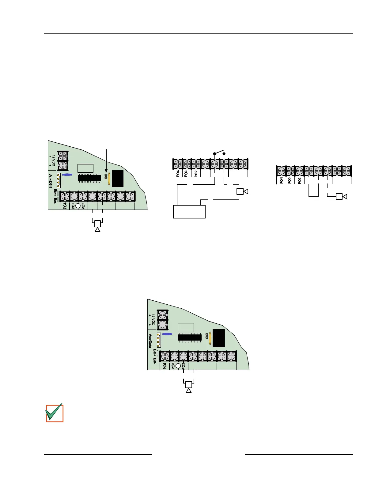
• Programmable Output 1 (PO 1): PO 1 terminals can be configured as an alarm power output. JP2-PO 1
Jumper must be closed. The default configuration for Programmable Output 1 makes it a dry contact,
Normally Open relay with PO 1 Jumper open (see Figure 25).
PO 1 Wiring (with PO 1 Jumper shorted)
R
Y
G
B
PO1
B L-1
+
-
JP2-PO1
Select
Short PO 1 Jumper
with Jumper Plug
Alrm
+ A
(+) (-)
PO 1 Dry Contact Wiring
(without PO 1 Jumper)
PO1
L-1
+ -
Alrm
+
DC Power Source
(+) (-)
A B
(+) (+)
(-)
PO 1 Positive Alarm
Trigger Wiring
PO1
L-1
+
-
Alrm
+
A B
(+)
Figure 25: PO 1 Wiring
• Programmable Output 2 (PO 2): Output PO 2 can be used with Alarm+ as a supervised siren driver. Connect
an approved 4 or 8 Ω siren. Alternatively, PO 2 can sink up to 500 mA 12 VDC. For larger loads, use a
Radionics D133 Relay Module or a Radionics D134 Dual Relay Module.
• Programmable Outputs 3 & 4 (PO 3 & PO 4): Outputs PO 3 and PO 4 can be configured for Alarm Output.
These outputs can sink up to 500 mA 12 VDC each. For larger loads, use a Radionics D133 Relay Module or
a Radionics D134 Dual Relay Module (see Figure 26).
R
Y
G
B
PO1
B L-1
+
-
JP2-PO1
Select
Alrm
+ A
(-) (+)
Figure 26: PO 2 - PO 4 Wiring
IMPORTANT
Use the Fire System Power Formula (see Section 5.4.1, Available Power) above to calculate the current
available for fire and combined fire/burglary systems.
On-board Outputs