Page 4845349D © 2002 Radionics
D6412/D4412 Installation Guide
D6412/D4412
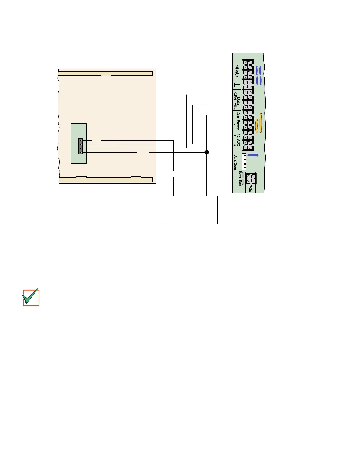
Back of Command Center
D6412/D4412 PCB
Y
G
B
R
Red
Yellow
Green
Black
Red
Yellow
Green
Black
External 12 VDC
Power Supply
+ -
Figure 34: External Power for Command Centers
11.3 D268/D269, D279 Independent Zone Control
You can program on-board points 2 to 8 so that the D268, D269 or D279 (or later versions) Independent Zone
Controls operate as independent point controls (arms and disarms the point).
See Point Index Configuration in the D6412/D4412 Program Entry Guide (P/N: 45351) for programming
information. See the installation literature that accompanies the D268, D269 and D279 (or later versions) for
wiring and operation instructions.
IMPORTANT
In order to use the D268, D269 or D279 (or later versions) Independent Zone Control, you must
program the panel’s on-board points for 1 k ΩΩ End of Line resistors. Points 2 to 8 must all be
supervised with 1 k ΩΩ resistors, even if an Independent Zone Control is only used for one point. See
Global Point Configuration in the D6412/D4412 Program Entry Guide (P/N: 45351) for programming
instructions. Only use on-board points 2-8 with an Independent Zone Control. No EOL resistor is used
on the points connected to the IZC.
Arming Devices