Page 35© 2002 Radionics
D6412/D4412 Installation Guide
45349D
D6412/D4412
Off-board Sensor Loops
DX2010 Side
Mounting Locations
R
Y
G
B
Alr m
+
PO1
L-1
+ -
L-2Com L-4ComL-3 L- 6C omL-5 L-8C o mL-7
T
T1
R1
AU X ILIARY
JP 1
Insta lle r
JP2 - PO1
Se lec t
A B
R
D6412/D4412 PCB
DX2010
Terminals
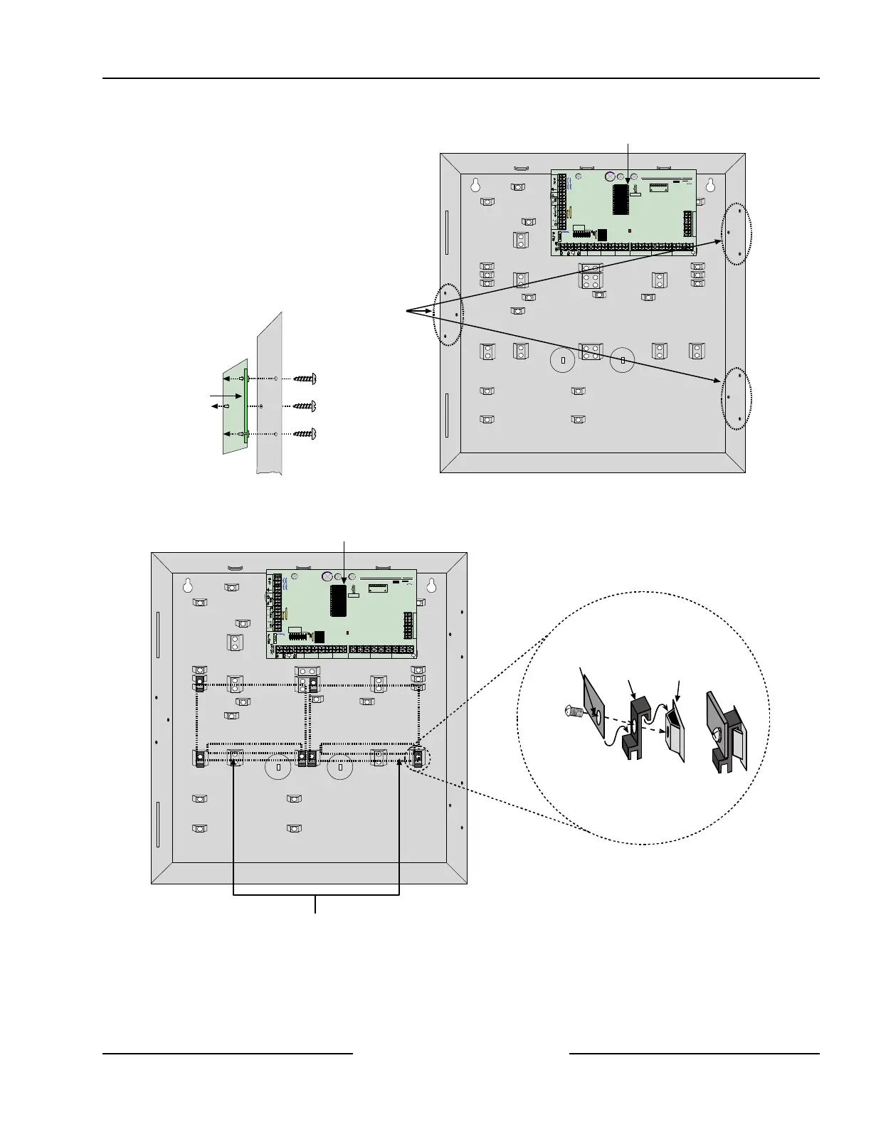
Enclosure Wall
Mounting Hardware
(supplied w/DX2010)
Figure 15: Installing the DX2010 in the Panel’s Enclosure
The DX2010 can also be mounted to the back wall of the control/communicator’s enclosure. See Figure 16.
Mounting Clip Assembly
Enclosure
Standoff
Mounting
Clip
Corner of
DX2010 PCB
=
R
Y
G
B
Alrm
+
PO1
L-1
+
-
L-2Com L-4ComL-3 L-6ComL-5 L-8ComL-7
T
T1
R1
AUXILIARY
JP1
Installer
JP2-PO1
Select
A B
R
Terminals
DX2010
Terminals
DX2010
D6412/D4412 PCB
Optional mounting locations for DX2010
inside Control/Communicator Enclosure
Figure 16: Optional Enclosure Mounting Locations for the DX2010