Page 45© 2002 Radionics
D6412/D4412 Installation Guide
45349D
D6412/D4412
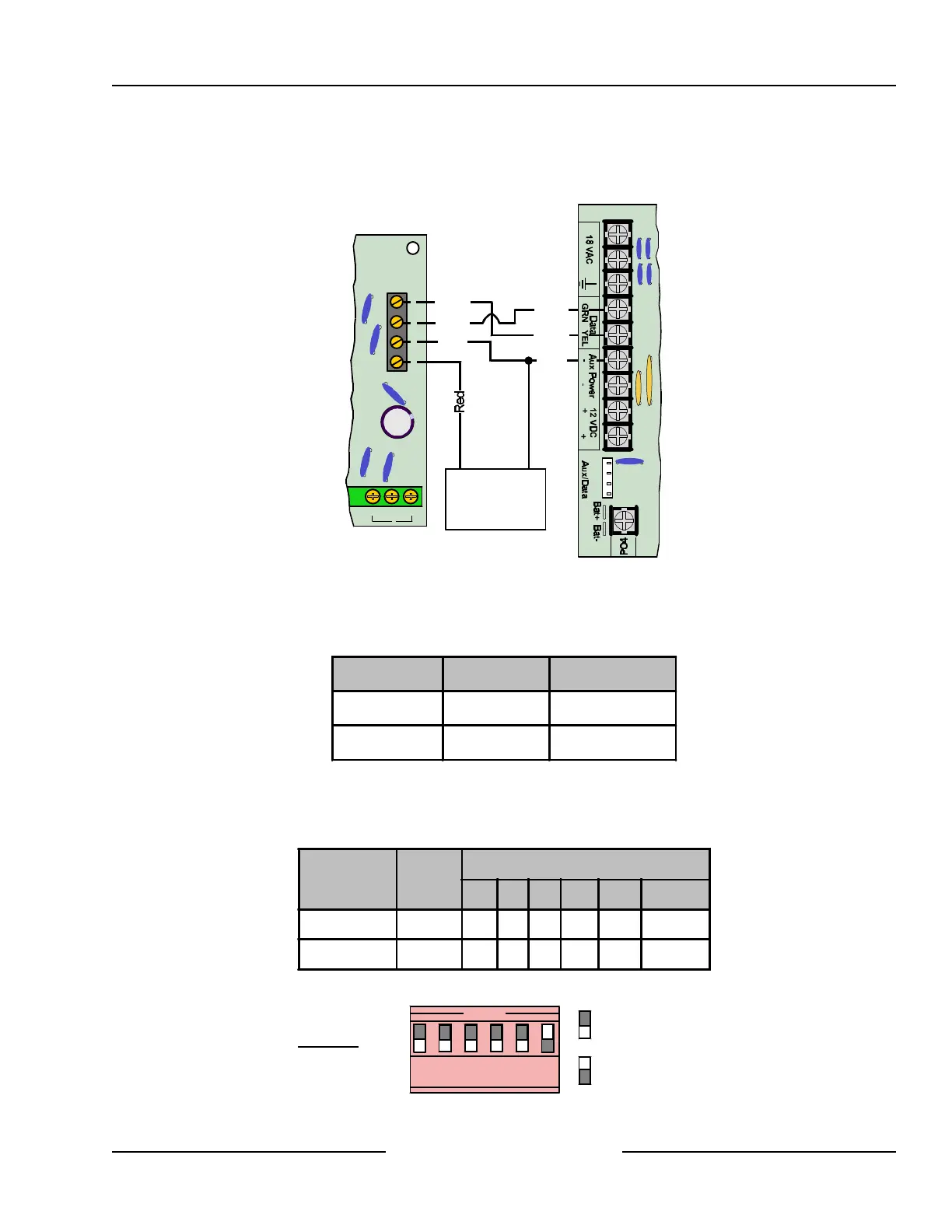
If you need to power the DX3010 from an external power source, connect it to the power source and the panel
as shown in Figure 30. See Section 4.3, External Power Supply, for external power supply restrictions.
Y
G
B
R
NC NOC
8
Y
B
R
G
Yellow
Yellow
Green
Green
Black
Black
DX3010
D6412/D4412
External 12 VDC
Power Supply
+ -
Figure 30: Wiring for External Power Supply
10.2.6 Address Programming
Each DX3010 module connected to the panel must have its address jumpers set to the address shown in Table
12.
Panel Output # SDI Address
D6412/D4412 5 to 12 SDI Address 150
D6412 only 13 to 20 SDI Address 151
Table 12: DX3010 Address Settings
Any time the address jumpers are changed, you must cycle the control panel power OFF and then ON for the
changes to take effect. Set the address jumpers as shown in the Table 13. “DN” indicates that the DIP switch is
CLOSED (Down). See Figure 31 for DIP Switch configuration.
Panel
SDI
Address
DIP Switch, X=DIP Switch is CLOSED
1 2 4 8 16 MODE
D6412/D4412 150 UP UP UP UP UP
DN
D6412 only 151
DN
UP UP UP UP
DN
Table 13: DX3010 Address Jumper Settings
=Switch CLOSED (Down)
=Switch OPEN (Up)
Example:
Module Address 150
OPEN
1 2 3 4 5 6
Figure 31: DX3010 Address DIP Switches
Off-board Outputs