Page 5245349D © 2002 Radionics
D6412/D4412 Installation Guide
D6412/D4412
12.3.1 DX4010 Installation
The intended installation location for the DX4010 is in the plastic enclosure that it is shipped in. This is a low-
profile, aesthetically appealing housing that can be placed on a desktop or similar surface.
Distance from the panel is determined by the total combined wire length of all devices (including keypads)
connected to the panels Data terminals. The combined total wire length must not exceed 1000 ft. (305 m) for
#22 AWG (0.8 mm), or 2,000 ft. (610 m) for #18 AWG (1.2 mm).
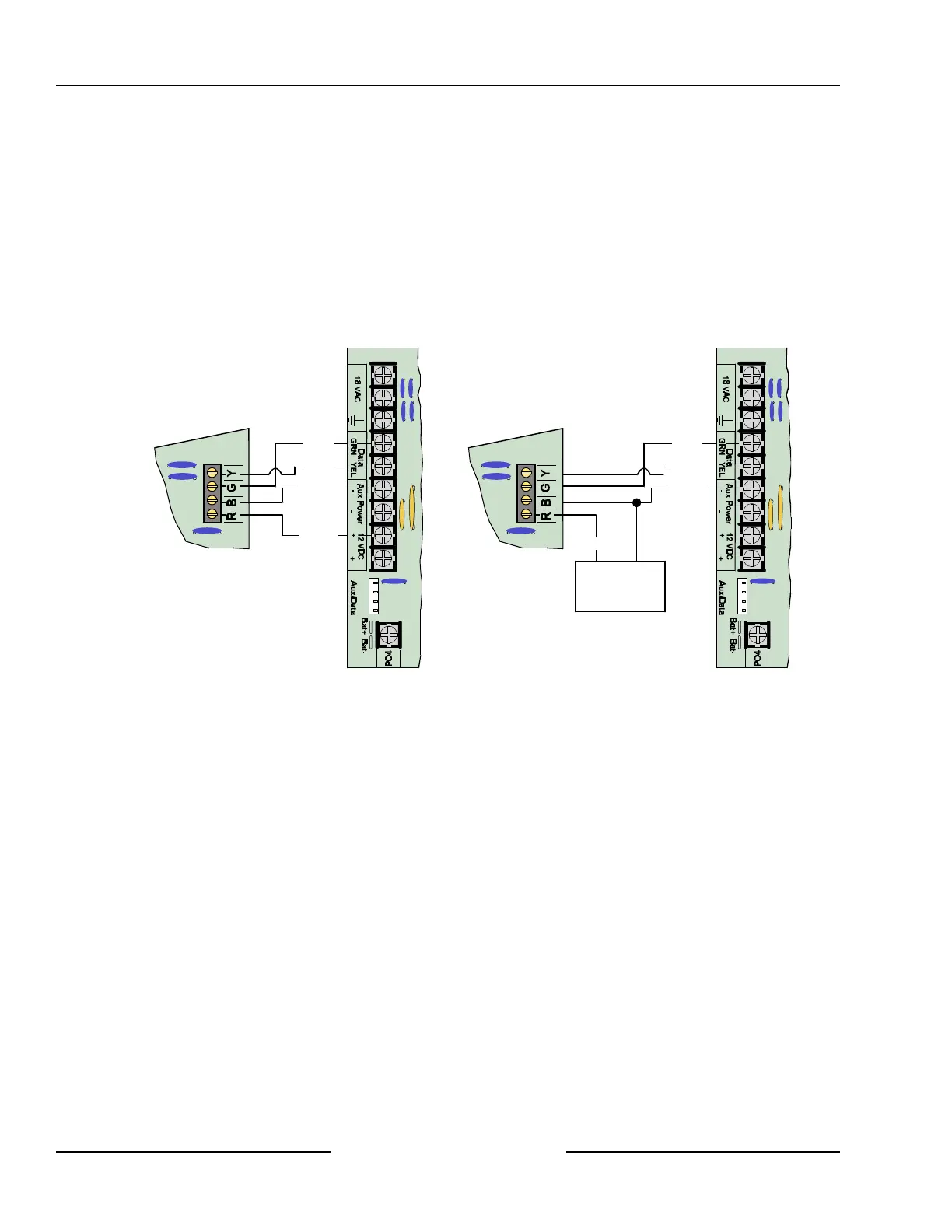
12.3.2 DX4010 to D6412/D4412 SDI Bus Wiring Connections
See Figure 39 for acceptable power wiring connections. See Section 4.3, External Power Supply, for external
power supply restrictions.
Y
G
B
R
D6412/D4412
DX4010 to D6412/D4412 Power Connections
DX4010
Red (+)
Black (-)
Yellow
Green
External 12 VDC
Power Supply
(+) (-)
Y
G
B
R
D6412/D4412
DX4010 to External Power Supply Connections
Black (-)
Yellow
Green
DX4010
Red (+)
Figure 39: DX4010 Power Connections
12.3.3 RAM IV Direct Connection
The DX4010 can be used to connect directly to the panel for RAM IV remote programming. It also allows the
user to perform diagnostic and history retrievals in RAM IV.
To connect directly to the panel for a RAM IV session, use these steps:
1. Make sure the DX4010’s Address DIP Switches are set to Address 0. See the DX4010 Installation Guide
(P/N: 49539) for address DIP Switch location and positioning.
2. Using a null modem cable (not included), connect the DX4010 to Com Port 1 or 2 (or an available Com
Port) on your computer. The DX4010 has a DB-9 male serial connector. If this does not fit your computer,
you will need an adapter.
3. Wire the flying leads of the colored cable connector (included with panel) to the DX4010’s SDI Bus
terminals. Plug the connector end onto the D6412/D4412. See Figure 40 for details.
4. Plug the connector end of the cable onto the panel PCB. See Figure 40 for details.
SDI Devices