Page 3045349D © 2002 Radionics
D6412/D4412 Installation Guide
D6412/D4412
The number of normally-open and/or normally-closed detection devices each sensor loop can supervise is
limited only by the resistance on the loop. The total resistance for wire length and contacts, minus the end-of-
line resistor, must not exceed 100 Ω.
You can determine the condition of the on-board sensor loops in the default configuration (single point, 2.2 k Ω
end-of-line resistor) by measuring the voltage across the point input terminal and one of the common terminals.
The sensor loops must be connected and the 2.2 k Ω end-of-line resistor in place.
D6412/D4412 Loops 2-8:
For a 2.21 k EOL resistor:
Open Loop: Greater than 7.7 VDC.
Normal Loop: Greater than 6.3 VDC, less than 7.3 VDC.
Shorted Loop: Less than 6.0 VDC.
For a 3.65 k EOL resistor:
Open Loop: Greater than 9.1 VDC.
Normal Loop: Greater than 7.7 VDC, less than 8.6 VDC.
Shorted Loop: Less than 7.3 VDC.
For a 1.0 k EOL resistor:
Open Loop: Greater than 5.0 VDC.
Normal Loop: Greater than 3.8 VDC, less than 4.7 VDC.
Shorted Loop: Less than 3.5 VDC.
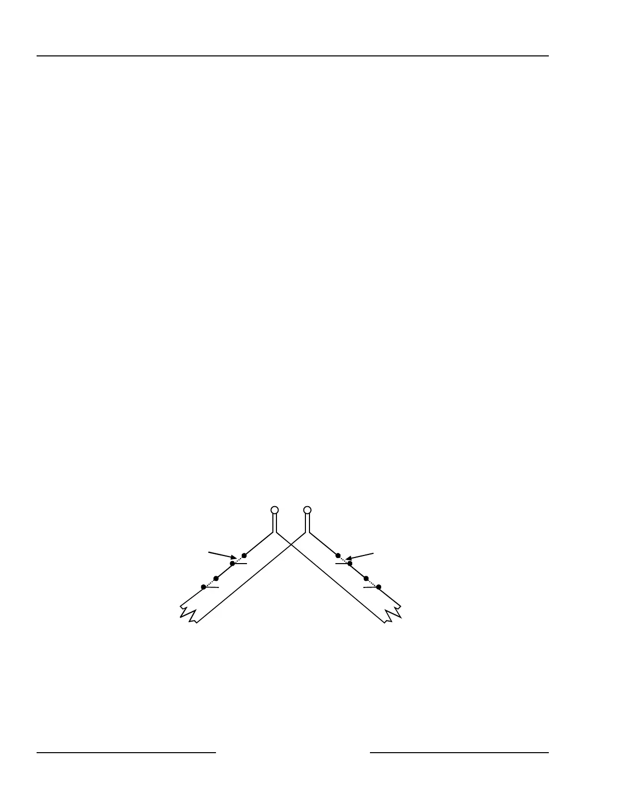
7.6 Doubled Point Configuration
When wiring the on-board sensor loops in the doubled point configuration, install the resistors of the appropriate
value (2.2 k Ω and 3.65 k Ω) as shown in Figure 13.
Each loop is monitored
as a separate point.
Open for alarm
otherwise
Normally Closed
Open for alarm
otherwise
Normally Closed
3.65 k
Ω
2.2 k
Ω
L-2 to L-8Common
(Point Doubling not available for Sensor Loop 1)
Onboard Locations
2 to 8
Onboard Locations
10 to 16
Figure 13: On-board Doubled Point Sensor Loop Wiring
Onboard Sensor Loops