Page 3645349D © 2002 Radionics
D6412/D4412 Installation Guide
D6412/D4412
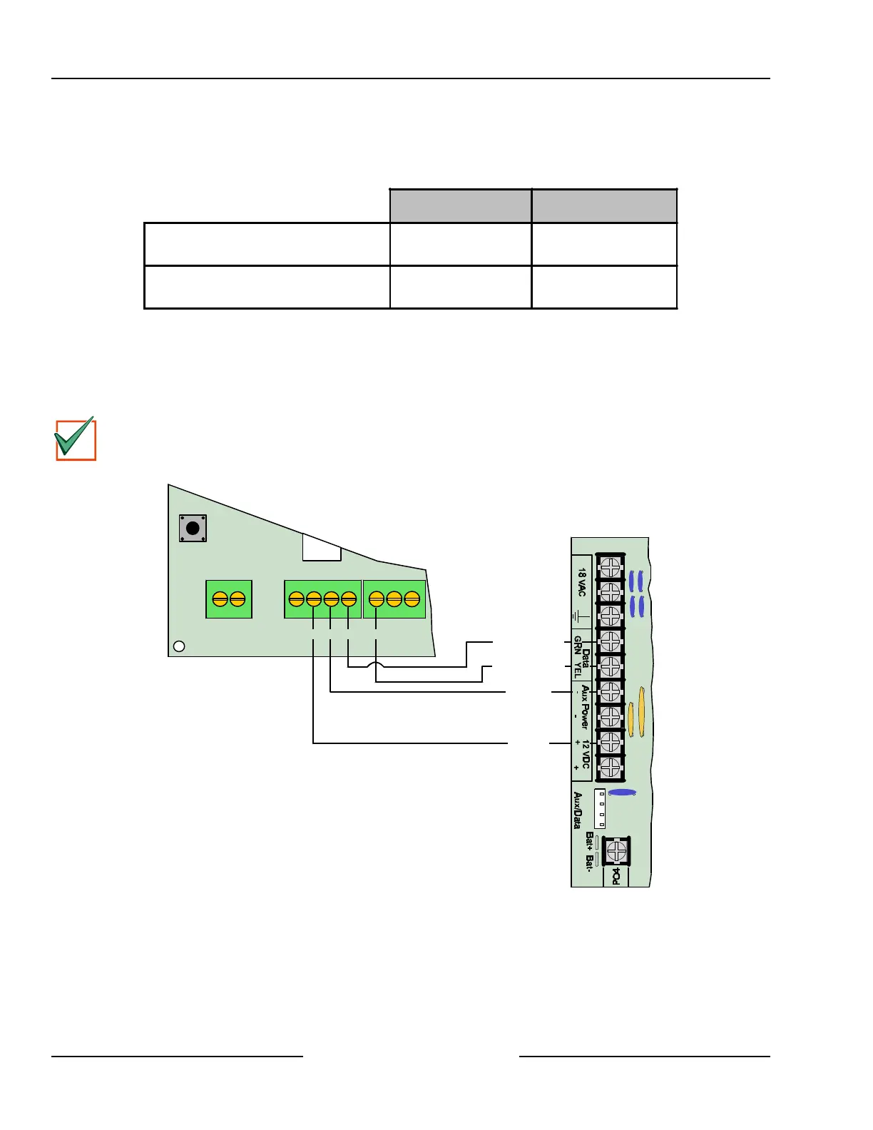
8.2.3 DX2010 to Panel SDI Bus Connections
Connect the panel’s Data and Aux Power terminals to the DX2010 module as shown in Figure 17. Refer to
Table 6 for the SDI bus wiring length requirements.
22 AWG (0.8 mm) 18 AWG (1.2 mm)
Panel to DX2010
DX2010 AUX Output NOT Used
1000 ft. (305 m)* 2000 ft. (610 m)*
Panel to DX2010
DX2010 AUX Output supplying 100 mA
100 ft. (30 m)** 250 ft. (76 m)**
Table 6: DX2010 Wire Lengths
* Wire length may be restricted by panel limitations. See the installation guide for more information.
** If the DX2010 is powered directly by an external auxiliary power supply (Figure 18), use the wire lengths
specified in the first row of Table 6.
The wire lengths shown in Table 6 must be shared by all devices connected to the terminals.
IMPORTANT
Do not use twisted pair or shielded cable. Do not share cable with the keypad lines. The maximum
distance may be limited to 250 ft. (75 m) if the Aux Output is used. See Section 8.2.4 “DX2010 Auxiliary
Output Connections.”
Y
G
B
R
D6412/D4412
+OUT- TMPR 1 COM
DX2010
R B YG
Red (+)
Black (-)
Green (Data)
Yellow (Data)
Figure 17: Wiring the DX2010 to the D6412/D4412
If you need to power the DX2010 with an external 12 VDC power supply, wire it as shown in Figure 18. See
Section 4.3, External Power Supply, for external power supply restrictions.
Off-board Sensor Loops