Page 3845349D © 2002 Radionics
D6412/D4412 Installation Guide
D6412/D4412
8.2.5 DX2010 Tamper Input Connections
Each DX2010 module provides an input for tamper devices. The tamper input is in addition to the point sensor
loops. Supervising an enclosure tamper does not consume a point. A fault on the tamper input is reported as a
tamper event for the SDI address the DX2010 is set to.
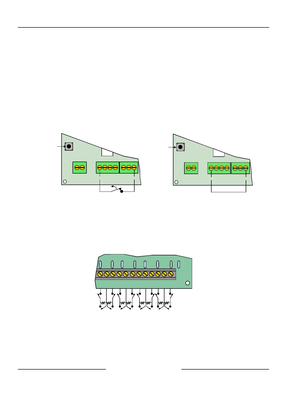
The tamper output may monitor external Normally Closed (N/C) tamper switches when wired as shown in Figure
20. The tamper circuit must be closed to provide proper DX2010 tamper supervision to the control panel. Do not
use an EOL resistor.
The DX2010 also provides an on-board tamper switch for use if the DX2010 is installed inside the AE20 plastic
enclosure. The cover tamper spring is supplied with the DX2010. The on-board tamper switch cannot be used if
the DX2010 is mounted inside the panel’s enclosure (wire the tamper input as shown in Figure 20 if installed in
the control panel’s enclosure).
If neither the tamper input or the on-board tamper switch is used, a wire jumper must be placed as shown in
Figure 20.
Use either the tamper input or the on-board tamper switch. Both cannot be used simultaneously.
1R B G Y
DX2010
+OUT- TMPR COM
On-board
tamper switch
Wire Jumper Location
1R B G Y
DX2010
+OUT- TMPR COM
On-board
tamper switch
Tamper Input Wiring
Figure 20: DX2010 Tamper Input Wiring
8.2.6 DX2010 Sensor Loop (Point) Connections
The DX2010 supports both Normally Open and Normally Closed contacts in the standard sensor loop
configuration. It supports Normally Closed contacts in the doubled sensor loop configuration.
The DX2010 is not designed for use with two-wire smoke detectors.
8.2.6.1 DX2010 Standard Sensor Loop Wiring
Wire as shown in Figure 21.
Use 2.21 k EOL
1 COM 2 3 COM 4 5 COM 6 7 COM 8
Figure 21: DX2010 Sensor Loop Wiring, Single Loop Configuration
Off-board Sensor Loops