Page 4045349D © 2002 Radionics
D6412/D4412 Installation Guide
D6412/D4412
For example: You want to use a DX2010 sensor loop for panel Point Location 9 (see Locations in the D6412/
D4412 Program Entry Guide (P/N: 45351) for a detailed description of locations and their relationship to points).
You must connect a DX2010 and set its address DIP switches to 102.
Any time the address DIP switches are changed, you must cycle the power to the module OFF and then ON for
the changes to take effect.
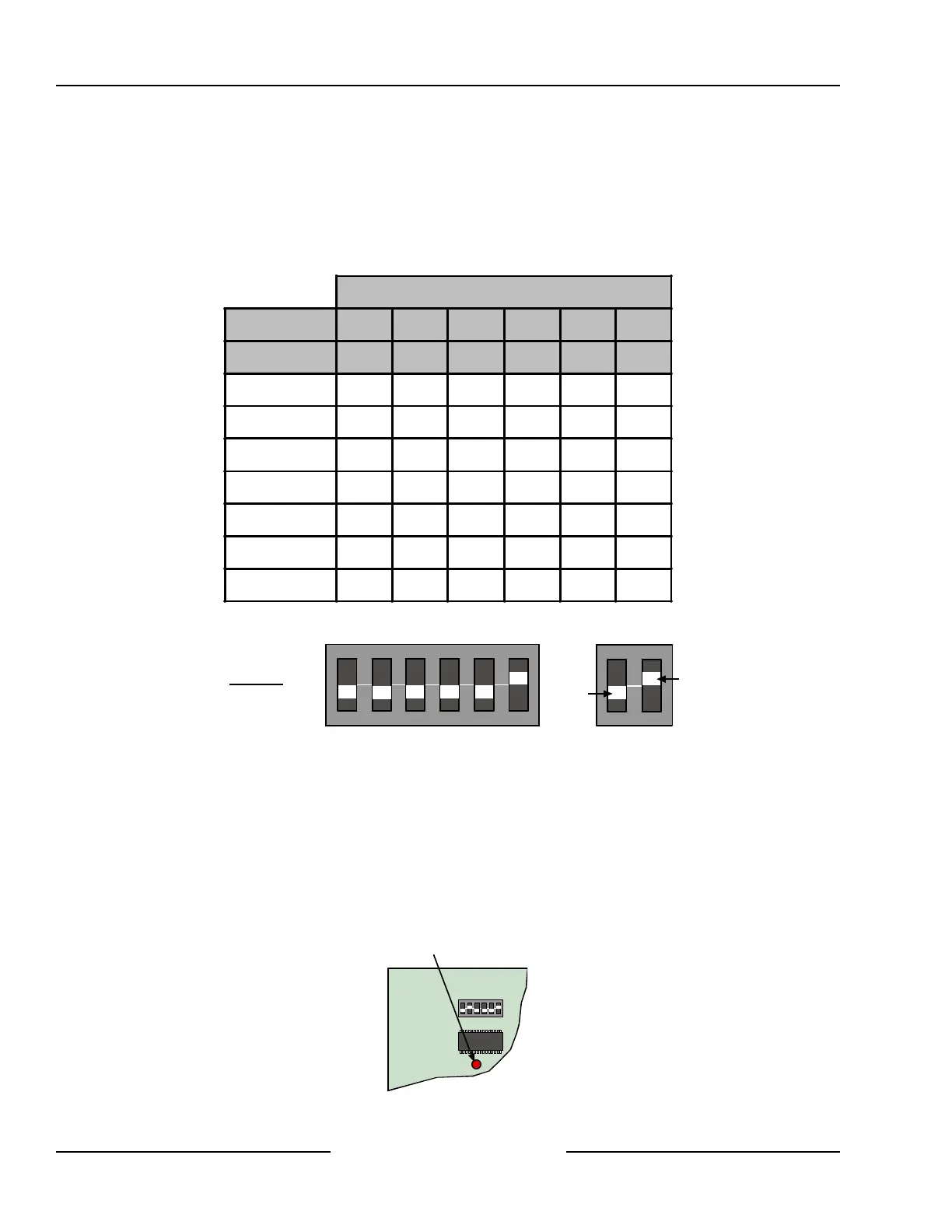
Set the address DIP switches as shown in the Table 10. See Figure 23 for proper DX2010 DIP switch
configuration.
DIP Switch Settings
DIP Switches S1 S2 S3 S4 S5 S6
Module Address 32 16 8 4 2 1
101 OFF OFF OFF OFF OFF OFF
102 OFF OFF OFF OFF OFF
ON
103 OFF OFF OFF OFF
ON
OFF
104 OFF OFF OFF OFF
ON ON
105 OFF OFF OFF
ON
OFF OFF
106 OFF OFF OFF
ON
OFF
ON
107 OFF OFF OFF
ON ON
OFF
Table 10: DX2010 Address Jumper Settings
ON
1 2 3 4 5 6
OFF
ON
Example:
Module Address 102
Figure 23: DX2010 DIP Switch Configuration
8.2.8 DX2010 Status LED
• One flash per second indicates normal operation.
• LED steady ON can indicate any of the following:
- G wire is not connected or there is a communications problem between the control panel and the DX2010.
- No locations (points) are assigned to the DX2010 with this address. See the Locations section in the
D6412/D4412 Program Entry Guide (P/N: 45351).
- Address on the DX2010 is not set correctly.
• LED OFF indicates that there is no power to the module.
ON
1 2 3 4 5 6
Status LED
Figure 24: DX2010 Status LED
Off-board Sensor Loops