Page 53© 2002 Radionics
D6412/D4412 Installation Guide
45349D
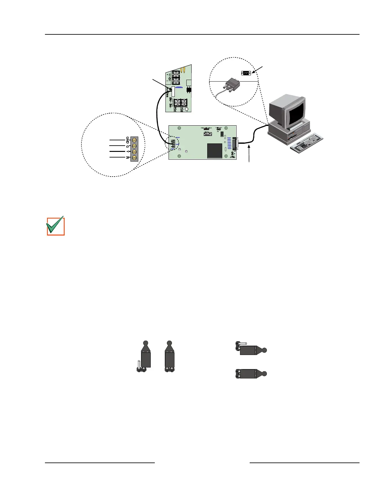
D6412/D4412
SDI Devices
Serial Port
Com Port
DX4010
Null Modem Cable
D6412/D4412
R
Y
G
B
JP2
Sel
AUX/Data
Connector Pin
Location
DX4010 SDI Bus
Black (GND)
Green
Yellow
Red
Figure 40: Creating a RAM IV Direct Connection
12.3.4 Configuration Jumpers
P2 – Diagnostic LED Pins
The diagnostic LEDs can be used for troubleshooting purposes. See Figure 41 for jumper plug placements.
IMPORTANT
The DX4010 will draw more current when the diagnostic LEDs are enabled. Do not enable the diagnostic
LEDs under normal operating conditions.
• BUS RX LED: SDI bus receive data from control panel.
• BUS TX LED: SDI bus transmit data to control panel.
• SER RX LED: RS-232 receive data from printer (or other serial device connected to DX4010).
• SER TX LED: RS-232 transmit data to printer (or other serial device connected to DX4010).
P3 – RS232 Cable Ground Pins
Some devices connected to the DB9 connector may cause a ground fault condition on the control/
communicator. If this occurs, removing the plug across the P3 jumper pins may clear the ground condition.
Some devices can cause a ground fault even if the P3 jumper plug is removed.
• P3 Jumper Pins Disabled: Isolate DB9 Shield from SDI Common (Black)
• P3 Jumper Pins Enabled: Connect DB9 Shield to SDI Common (Black)
Diagnostic LED Pins (P2)
Disabled Enabled
Cable Ground Pins (P3)
Disabled
Enabled
Figure 41: DX4010 P2/P3 Jumper Pin Settings