Page 5445349D © 2002 Radionics
D6412/D4412 Installation Guide
D6412/D4412
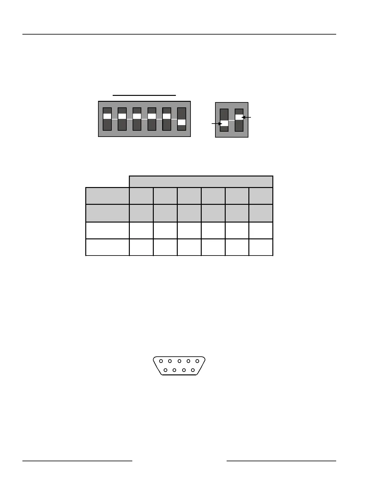
Address DIP Switches
Use the address DIP switches to assign Address 250 to the DX4010 when a serial device is connected to it. Set
the DIP switches to Address 0 (zero) when preforming a remote programming direct connection. See Figure 42
for proper DX4010 DIP Switch positioning, and Table 16 for DX4010 address settings.
ON
1 2 3 4 5 6
1 2 4 8 16 M
O
D
E
OFF
ON
Address 0 (zero) Settings
Figure 42: DX4010 DIP Switch Orientation
DIP Switch Settings
DIP Switches S1 S2 S3 S4 S5 S6
Module
Address
1 2 4 8 16 MODE
0 ON ON ON ON ON OFF
250 ON ON ON ON ON ON
Table 16: DX4010 Address Settings
12.3.5 Supervision
Supervision includes proper operation of the SDI bus, printer paper supply, and serial printer (or device)
selected (on-line).
The panel sends an SDI missing report if it fails to communicate with the DX4010 module.
12.3.6 DX4010 Module’s DB9 Connector
The DB9 Pins are configured as follows:
1 DCD 4 DTR 7 RTS
2 RxD 5 GND 8 CTS
3 TxD 6 DSR 9 RI
1 2 3 4 5
6 7 8 9
Figure 43: DX4010 DB9 Connector Layout
SDI Devices