Page 4645349D © 2002 Radionics
D6412/D4412 Installation Guide
D6412/D4412
11.0 Arming Devices
11.1 Description
Command Centers, maintained or momentary contact keyswitches, Premises RF arming devices, or any
combination are used to arm and disarm areas. The D6412 may contain up to four areas (up to two areas on the
D4412) that can be armed and disarmed individually.
11.2 Command Centers
A Radionics Command Center is a 4-wire SDI device used to arm and disarm areas, annunciate complete
system status, initiate system tests, and control many functions of the security system.
The panel can supervise up to eight wired Command Centers and 4 RF Keypads. The panel transmits a serial
device trouble report, SDI MISSING in the Modem IIIa
2
format or SYS PERIPHERAL TROUBLE in the
CONTACT ID format, if it loses communication with a wired supervised Command Center. RF Keypads are
shown as missing by SDI address. See RF Keypads in the D6412/D4412 Program Entry Guide (P/N: 45351).
SYSTEM FAULT appears in any Command Center with text display capability that loses communication with the
panel. A system trouble appears at all other Command Centers connected to the system. SYSTEM FAULT also
appears for approximately 10 seconds during power-up.
See Command Center in the D6412/D4412 Program Entry Guide (P/N: 45351) for complete programming and
operation details for Command Centers.
11.2.1 Assigning the Command Center an Address
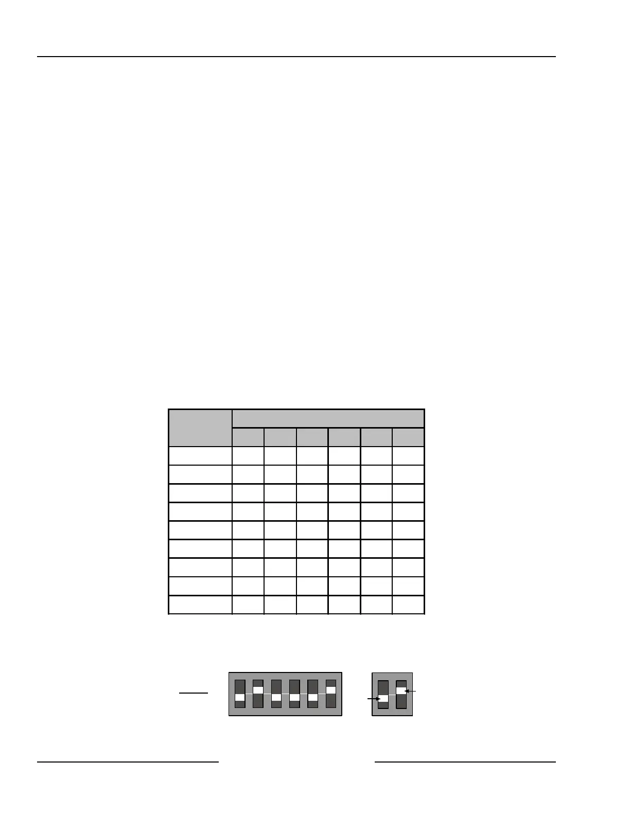
On-board DIP switches are used to assign a unique address to the Command Center. Command Centers 1 to 8
are assigned to SDI address 1 to 8. See Command Centers in the D6412/D4412 Program Entry Guide (P/N:
45351) for a complete description of command center programming (area assignment, etc.).
Table 14 shows the correct address setting for each Command Center address. See Figure 32 for proper
Command Center DIP switch orientation.
SDI Address
Switch Number, X = Switch On
1 2 4 8 16 MODE
0* OFF OFF OFF OFF OFF OFF
1
ON
OFF OFF OFF OFF
ON
2 OFF
ON
OFF OFF OFF
ON
3
ON ON
OFF OFF OFF
ON
4 OFF OFF
ON
OFF OFF
ON
5
ON
OFF
ON
OFF OFF
ON
6 OFF
ON ON
OFF OFF
ON
7
ON ON ON
OFF OFF
ON
8 OFF OFF OFF
ON
OFF
ON
Table 14: Command Center Address Assignments DIP Switch Settings
* Address 0 is reserved for the installer’s keypad. This keypad is not intended for permanent installation and
should remain on-premises for future programming sessions. See Section 13.0, Installer’s Keypad and
Installer’s Mode, for more information.
ON
1 2 3 4 5 6
1 2 4 8 16 MODE
ADDRESS
OFF
ON
Example:
Module Address 2
Figure 32: Command Center DIP Switch Orientation
Arming Devices