Page 39© 2002 Radionics
D6412/D4412 Installation Guide
45349D
D6412/D4412
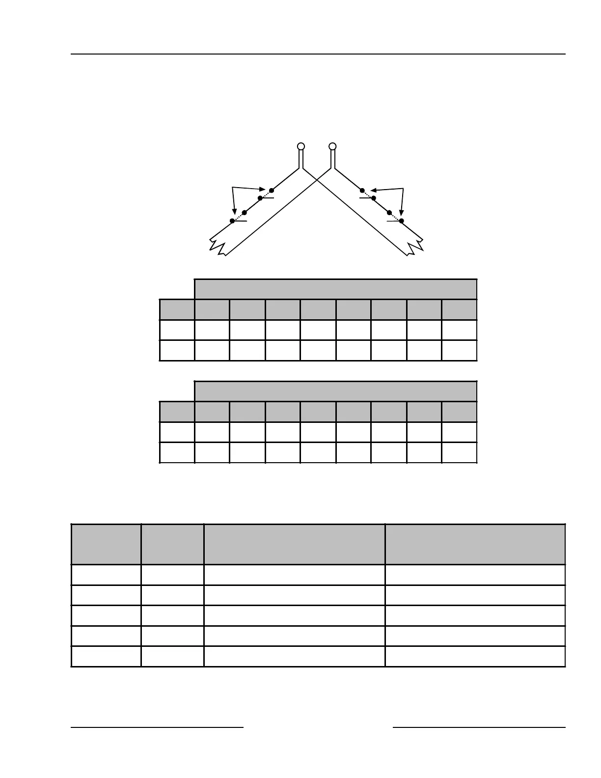
8.2.6.2 DX2010 Doubled Sensor Loop (Point) Wiring
Wire as shown in Figure 22.
Each loop is monitored
as a separate point.
Open for alarm
otherwise
Normally Closed
Open for alarm
otherwise
Normally Closed
2.2 k
Ω
3.65 k
Ω
Input
Terminals
1 to 8
Common
DX2010 Inputs
(See Tables 7 & 8)
DX2010 Inputs
(See Table 7)
Figure 22: DX2010 Sensor Loop Wiring, Doubled Loop Configuration
DX2010 Sensor Loop
EOL 1 2 3 4 5 6 7 8
3.65 k 9 10 11 12 13 14 15 16
2.2 k 17 18 19 20 21 22 23 24
Table 7: DX2010 Address 106
DX2010 Sensor Loop
EOL 1 2 3 4 5 6 7 8
3.65 k 25 26 27 28 29 30 31 32
2.2 k 33 34 35 36 37 38 39 40
Table 8: DX2010 Address 107 (for D6412 only)
8.2.7 DX2010 Address Programming
Each DX2010 module connected to the panel must have its address jumpers set to the addresses shown in
Table 9.
Panel Location #
For Standard Sensor Loop:
Set Location's 'Device' Parameter to '2'
Set DX2010 Address as shown below
For Doubled Sensor Loop:
Set Location's 'Device' Parameter to '3'
Set DX2010 Address as shown below
D6412/D4412 1 to 8 SDI Address 101
D6412/D4412 9 to 16 SDI Address 102 SDI Address 106
D6412/D4412 17 to 24 SDI Address 103 SDI Address 106
D6412 only 25 to 32 SDI Address 104 SDI Address 107
D6412 only 33 to 40 SDI Address 105 SDI Address 107
Table 9: DX2010 Address Settings
Off-board Sensor Loops