Page 47© 2002 Radionics
D6412/D4412 Installation Guide
45349D
D6412/D4412
Arming Devices
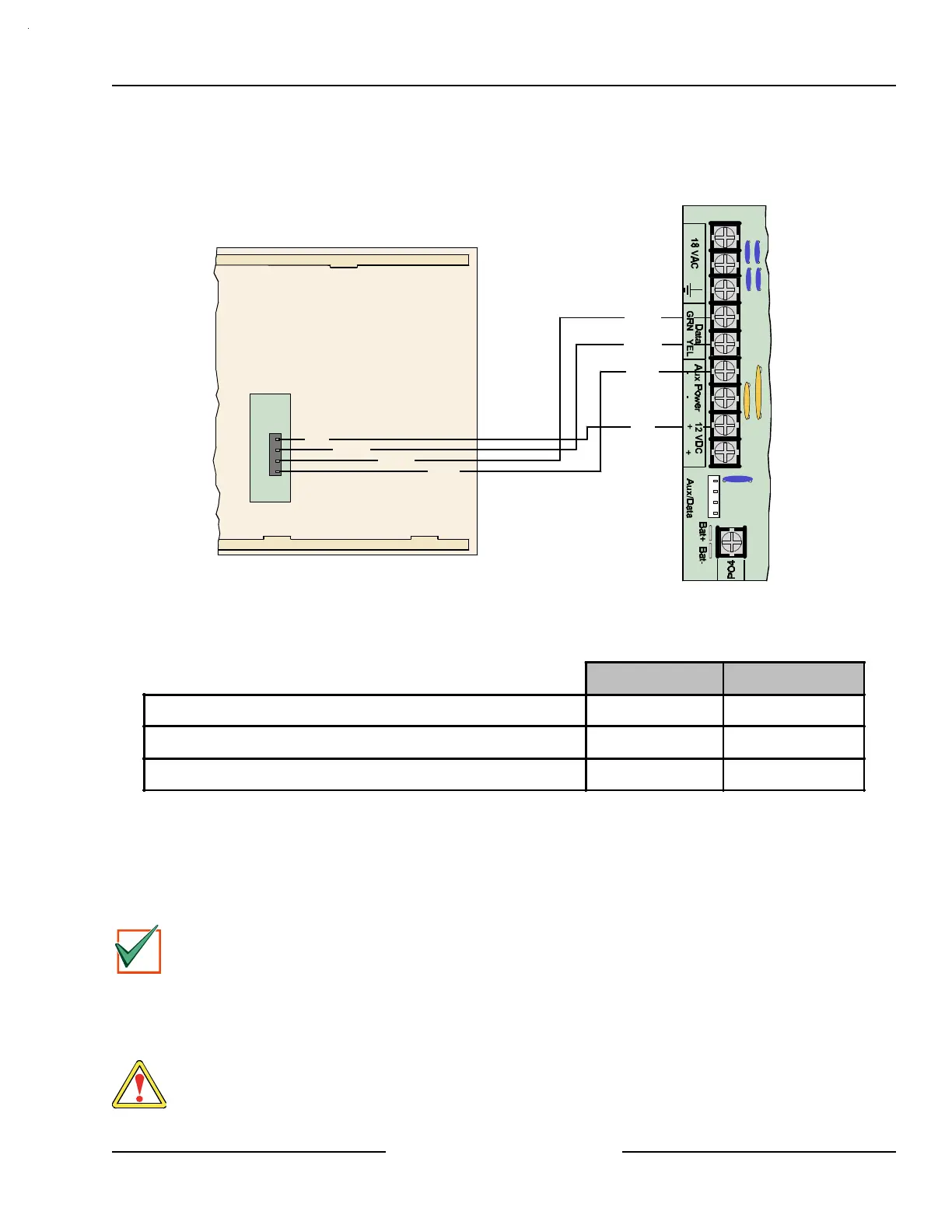
11.2.2 Command Center Installation
Consult the Command Center installation manual for installation and mounting instructions. Command Centers
connect to the panel in parallel as shown in Figure 33.
Back of Command Center
D6412/D4412 PCB
Y
G
B
R
Red
Yellow
Green
Black
Red
Yellow
Green
Black
Figure 33: Wiring Command Centers to the D6412/D4412
Refer to Table 15 for panel SDI Bus to Command Center wiring length requirements.
#22 AWG (0.8 mm) #18 AWG (1.2 mm)
D6412/D4412 to D621/D623 1000 ft. (305 m) 2000 ft. (610 m)
D6412/D4412 to D625* 225 ft. (69 m) 600 ft. (183 m)
D6412/D4412 to D621/D623/D625 using an External Power Supply 1000 ft. (305 m) 2000 ft. (610 m)
Table 15: Command Center Wire Lengths
* Due to higher current requirements for the D625 Vacuum Fluorescent Command Center, the wire lengths
shown in Table 15 must be used when wiring it from the control panel.
If an external power supply is used, follow the lengths as shown in Table 15.
Review Section 5.0, Power Outputs, to determine the total power output requirements for your system. You may
need to add one or more External Power Supply Modules for the number of Command Centers you want to use.
Figure 34 shows an external power supply powering Command Centers in a stand-alone configuration.
IMPORTANT
For UL certificated accounts, use a UL listed power supply.
See Section 4.3, External Power Supply, for external power supply restrictions.
Figure 34 shows the common from the External Power Supply Module connected to both the Command
Centers’ common and the common on the Control/Communicator.
A stand-alone power supply powering any device connected to the panel must also be connected to the Aux -
(Aux negative) terminal on the panel.
WARNING
Do not connect the stand-alone power supply to earth ground.