Page 29© 2002 Radionics
D6412/D4412 Installation Guide
45349D
D6412/D4412
R
Y
G
B
Alrm
+
PO1
L-1
JP2-PO1
Select
2.21 k
EOL
Resistor
-
+
Smoke
Detector
EOL Relay
Aux (+)
Aux (-)
A B
D285/D285TH w/
D292 Base
D275
End-of-Line Module
Remove
Jumper Plug
from JP2
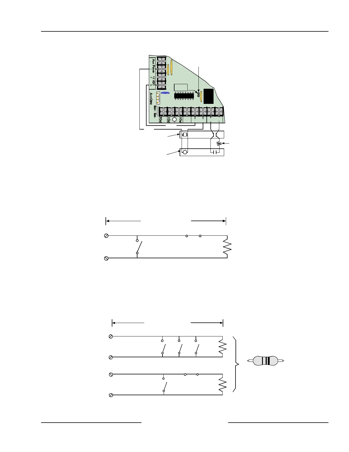
Figure 10: Typical Four-Wire Smoke Detector Wiring
7.4 Sensor Loop 1 Configuration
Sensor Loop 1 can be used for applications other than a fire point. This sensor loop cannot be used for point
doubling and must be terminated with a 2.21 k Ω EOL resistor (P/N: 25899).
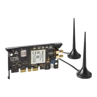
Loop resistance limits the number of Normally-Open and/or Normally-Closed detection devices that each sensor
loop can supervise. The total resistance for wire length and contacts, minus the end-of-line resistor, must not
exceed 100 Ω.
+
100 OHMS MAXIMUM
-
L1
2.21 k
Ω
EOL Resistor
(P/N: 25899)
COMBINATION: NORMALLY OPEN CONTACTS
AND NORMALLY CLOSED CONTACTS
Figure 11: Sensor Loop 1 Wiring
7.5 Single Point Configuration (Points 2-8)
When wiring the on-board sensor loops in the single point configuration, install the resistor of the appropriate
value (2.2 k Ω and 3.65 k Ω are provided) at the far end of the sensor loop to provide a reference for
supervision. You can connect dry contact sensing devices in series (normally-closed) and/or in parallel
(normally-open) to any of these loops (see Figure 12).
POINT INPUT
TERMINAL
COMMON
POINT INPUT
TERMINAL
COMMON
NORMALLY OPEN CONTACTS
COMBINATION: NORMALLY OPEN CONTACTS
AND NORMALLY CLOSED CONTACTS
100 OHMS MAXIMUM
EOL Resistor P/N: 47819
2.2 k Ω
L2 to L8
Figure 12: Single Point Sensor Loop Wiring
Onboard Sensor Loops