Page 7© 2002 Radionics
D6412/D4412 Installation Guide
45349D
D6412/D4412
1.0 Introduction
This manual addresses the installation of the D6412 and D4412 Control/Communicators only, and should not
be used for any other panel.
1.1 Manual Organization
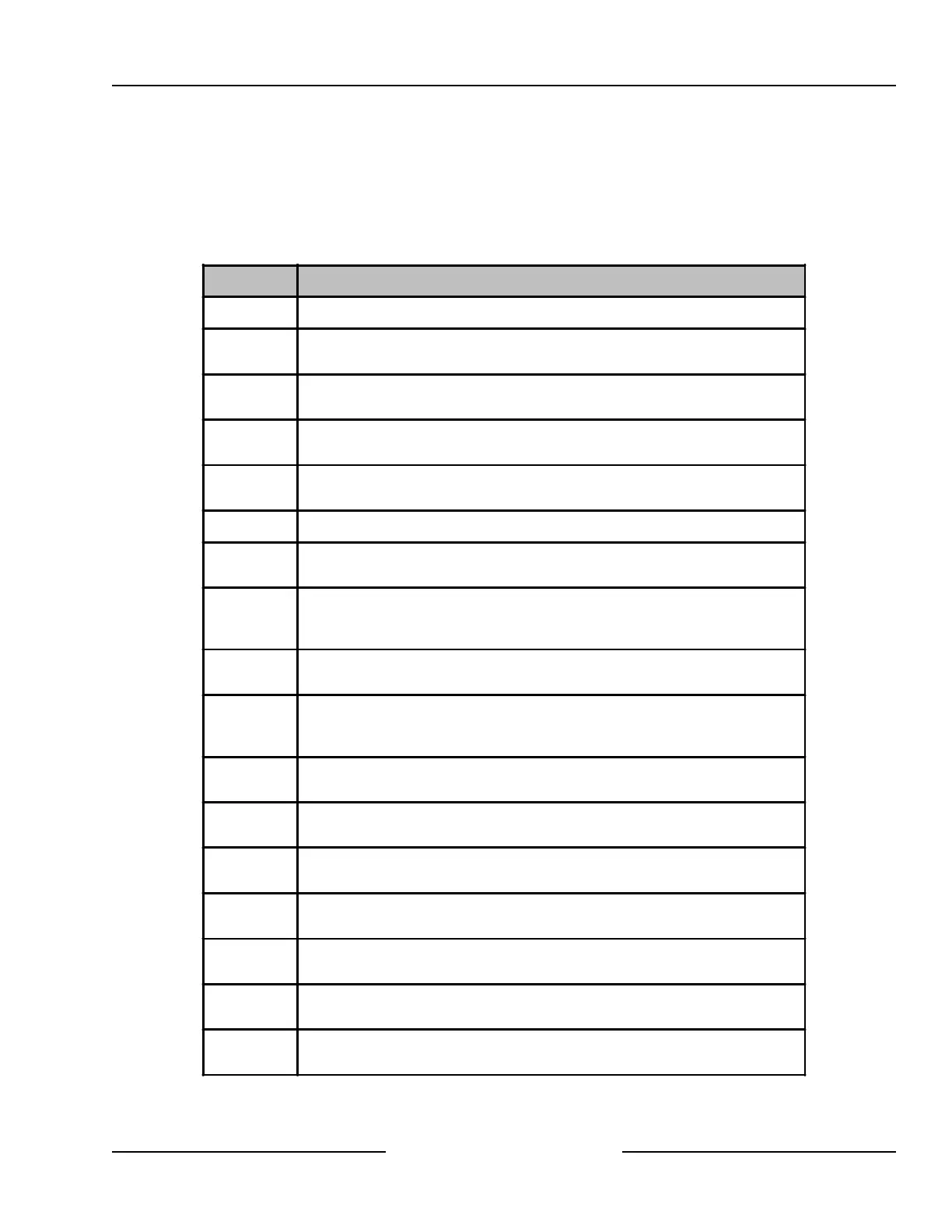
This manual is divided into 16 sections with seven appendices. Table 1 contains a summary of each section.
Section Description
1.0 Introduction - this section.
2.0
Overview - provides an overview of the D6412/D4412 Control/Communicators,
including operational specifications, standard and new features.
3.0
Installation - provides basic installation instructions, everything needed to get the
panel powered up and ready for programming.
4.0
Power Supply - provides information on the primary and secondary power
soruces and instructions on connecting them.
5.0
Power Outputs - provides information on the available powered outputs, including
the alarm output and the built-in siren driver.
6.0 Telephone Connections - provides information on connecting the phone line.
7.0
On-Board Sensor Loops - provides information on the eight on-board sensor
loops available on the D6412/D4412.
8.0
Off-Board Sensor Loops - provides information on available off-board sensor
loops, including detailed instructions for connecting the DX2010 Point Expansion
Module.
9.0
On-Board Outputs - provides information on the four on-board programmable
outputs.
10.0
Off-Board Outputs - provides information on available off-board programmable
outputs, including detailed instructions for connecting the DX3010 OctoOutput
Module.
11.0
Arming Devices - provides information on command centers, keyswitches and
independent zone controls.
12.0
SDI Devices - provides descriptions and installation instructions for various
optional modules that connect to the D6412/D4412's data terminals (SDI bus).
13.0
Installer's Keypad and Installer Mode - provides information for using an
Installer's Keypad and the Installer's Mode.
14.0
Installation Label
- a copy of the installation label found inside of the
D6412/D4412's enclosure.
15.0
Terminal Quick Reference - a chart providing a short description of each
D6412/D4412 terminal.
16.0
Troubleshooting - provides potential solutions to a variety of commonly
encountered problems.
Appendices
A: Approved Applications and Compliance Guide
B: SDI Address Chart
Table 1: D6412/D4412 Installation Guide Manual Organization
Introduction