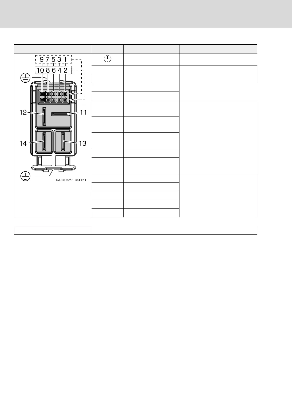
View Connection Signal name Function
PE Equipment grounding conductor
14 L- Power supply, DC 750 V, 25 A
13 L+
12 0V 42 V supply, max. 15 A
11 42V
10 Ext_SI_Ch1_In (X103.1)
Ext_SI_Ch1 (X103.2)
Control signals (24 V)
9 Ext_GND_In (X103.1)
Ext_GND (X103.2)
8 Ext_SI_Ch2_In (X103.1)
Ext_SI_Ch2 (X103.2)
7 bModulbus
6 bE_Stop_In (X103.1)
bE_Stop_Out (X103.2)
5 Shield Multi-Ethernet
4 RxD-
3 TxD-
2 TxD+
1 RxD+
Contact design Pins at device
Tab. 6-21: Function, pin assignment, properties
Notes on installation
● Exclusively operate KSM02/KMS02/KMS03 at a KCU02 or KMV03.
● Always connect the hybrid cable of KCU02 to the connection point
X103.1 of the first KSM02/KMS02 of a drive line.
● Hybrid cables contain power lines and control lines. Always route hybrid
cables in such a way that the hybrid cables are protected against
external damage (in accordance with EN 61800‑5‑1 and EN 61800‑5‑2).
Notes on operation
● Do not remove connectors when the component has been powered. Do
not plug in connectors when the component has been powered.
● Avoid removing and plugging in the hybrid cable unless it is necessary.
Allowed number of plugging cycles: ≤ 50
164/407
Connection points
IndraDrive Mi Drive Systems with KCU02, KSM02,
KMS02/03, KMV03, KNK03, KLC03
Bosch Rexroth AG R911335703_Edition 04