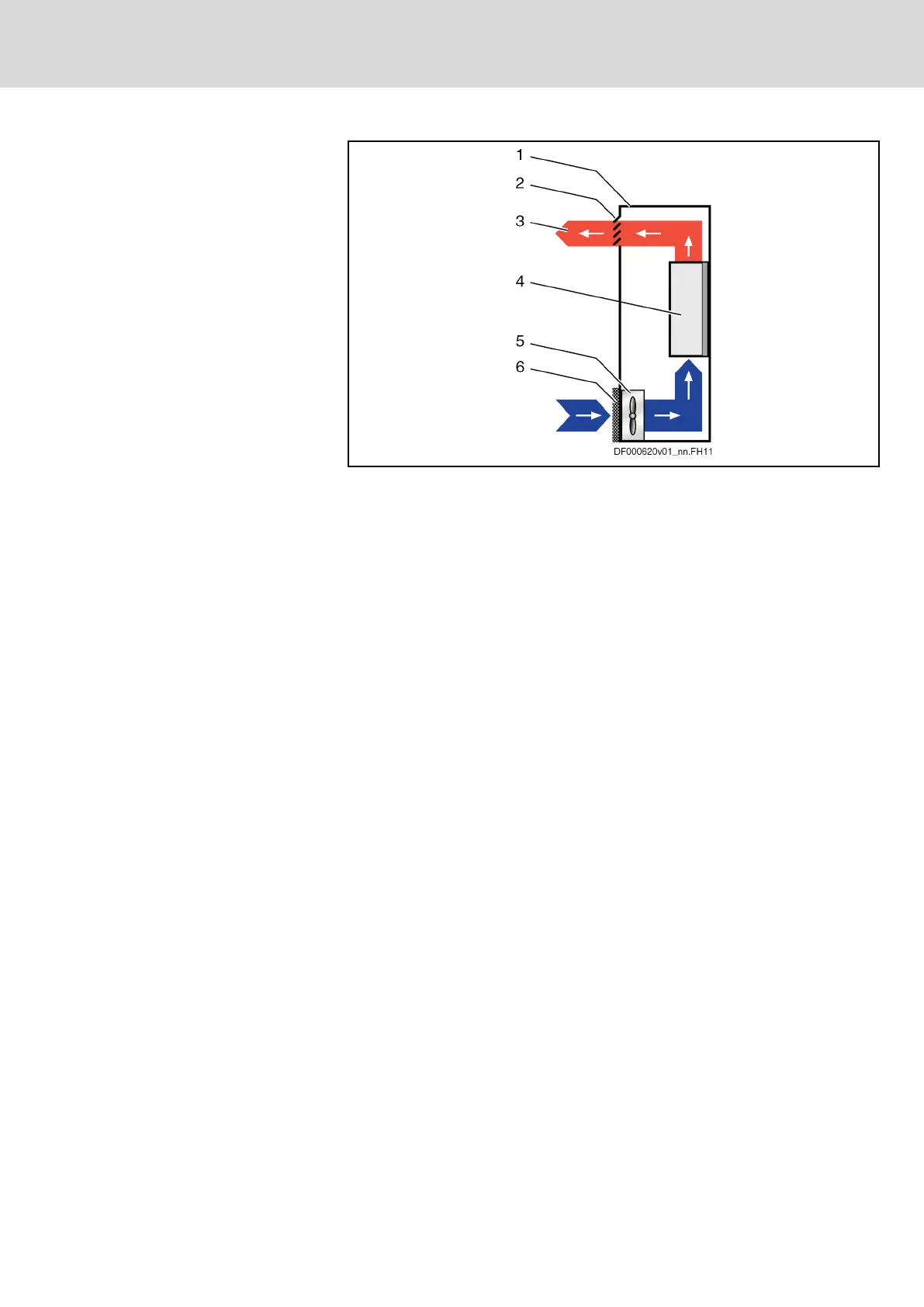
Control cabinet ventilation (sche‐
matic diagram)
1 Control cabinet
2 Air outlet opening
3 Heat discharge
4 Device in control cabinet
5 Control cabinet fan
6 Filter at air intake opening
Fig. 4-1: Control cabinet ventilation (schematic diagram)
Only clean air gets into the control cabinet through the filter at the air intake
opening. The control cabinet fan behind the air intake opening conveys the
air into the control cabinet and generates overpressure in the control cabinet.
The overpressure prevents unclean air from getting into the control cabinet
through possibly existing leaky points (leaky cable ducts, damaged seals,
etc.).
IndraDrive Mi Drive Systems with KCU02, KSM02,
KMS02/03, KMV03, KNK03, KLC03
57/407
General data and specifications
R911335703_Edition 04 Bosch Rexroth AG