17
Making the Connections
Chapter 1
• Howling could be produced depending on the location of microphones relative to
speakers. This can be remedied by:
1. Changing the orientation of the microphone(s).
2. Relocating microphone(s) at a greater distance from speakers.
3. Lowering volume levels.
• If you are going to output in mono, connect the cable only to the OUTPUT R
(MONO) jack.
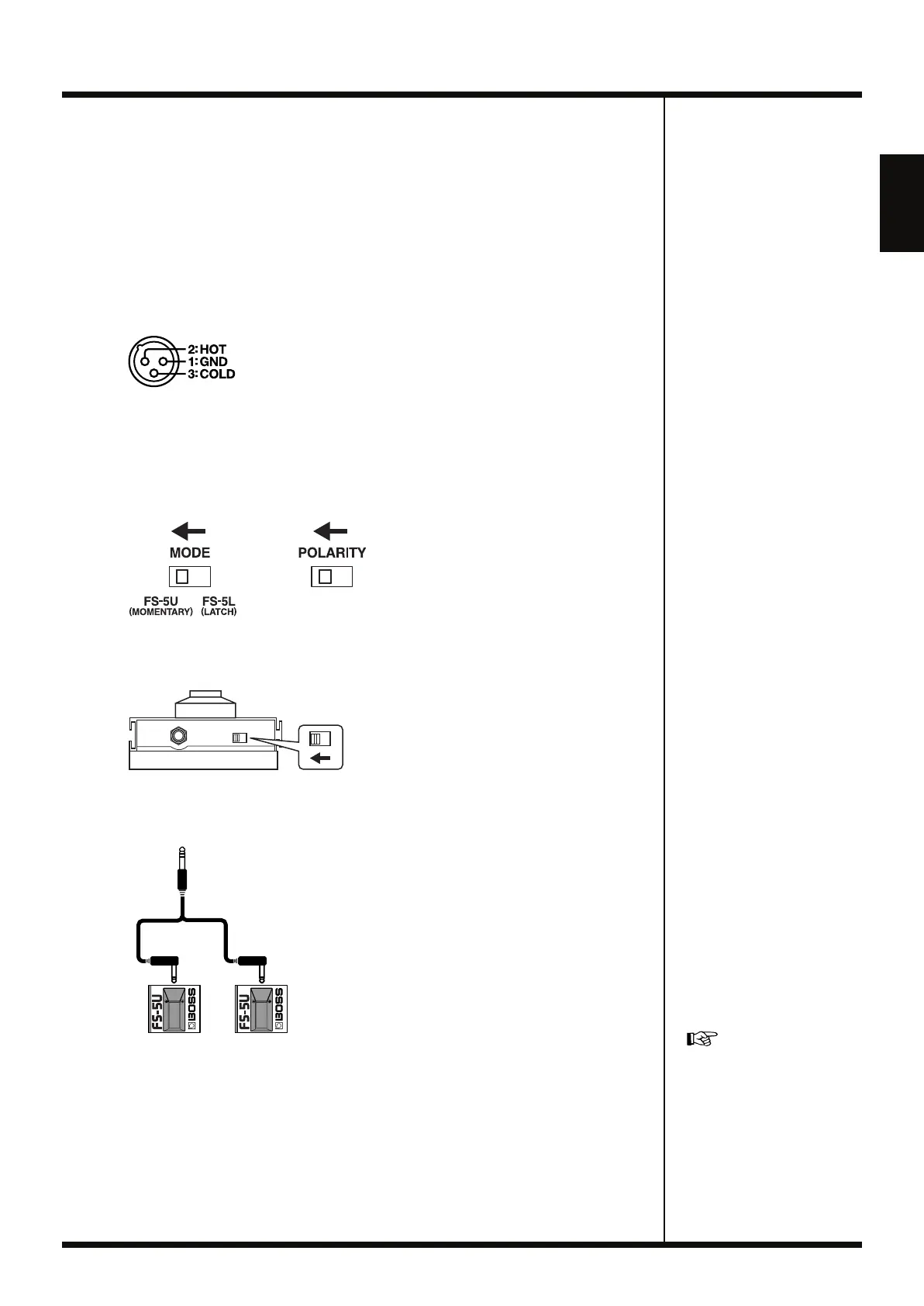
• This instrument is equipped with balanced (XLR) type jacks. Wiring diagrams for
these jacks are shown below. Make connections after first checking the wiring
diagrams of other equipment you intend to connect.
fig.01-020
• If connecting an EXP pedal to the EXP/CTL 3,4 PEDAL jack, set the minimum
volume to the MIN position.
• If connecting an FS-6 foot switch (optional; sold separately) to the CTL 1,2 PEDAL
jack or the EXP/CTL 3,4 PEDAL jack, set the MODE switch and POLARITY switch
as shown below.
fig.01-030
• If connecting an FS-5U foot switch (optional; sold separately) to the CTL 1,2 PEDAL
jack or the EXP/CTL 3,4 PEDAL jack, set the POLARITY switch as shown below.
fig.01-040
• Using the PCS-31L special connection cable (from Roland; sold separately) enables
you to connect two FS-5U switches.
fig.01-050
• When using an EXP pedal connected to the EXP/CTL 3,4 PEDAL jack, make the
settings described in “Pedal Settings” (p. 70).
• When using a foot switch connected to the CTL 1,2 or EXP/CTL 3,4 jacks, make the
settings described in “Pedal Settings” (p. 70).
Polarity
Switch
PCS-31L
White Red
For detailed instructions on
using the RC-50 with a
computer connected to the
USB connector, refer to
“Chapter 9 Connecting to
Computers” (p. 79).
RC-50_e.book 17 ページ 2009年4月10日 金曜日 午後1時17分
 Loading...