70
Pedal Settings
While the RC-50 already features seven pedals, you can also switch
the pedal functions of the TEMPO pedal and UNDO/REDO pedal.
Rather than using the pedal for UNDO and REDO, you can switch
the pedal to perform another desired function, for example to
increase patch numbers one by one.
In addition, by connecting external pedals to the CTL 1, 2 PEDAL
and EXP/CTL 3, 4 PEDAL jacks, you can use the external pedals to
control functions that are difficult to handle using the RC-50’s pedals
alone, making operation of the RC-50 easier and more convenient.
Pedal functions operate in accordance with system settings, that is,
settings that are shared by and applied the same way to all of the
RC-50’s functions and that remain the same regardless of the patch
selected, and patch settings, or settings that are used to select
different functions for each individual patch.
In each parameter, you select whether the system settings or the
patch settings are to be applied, giving you the freedom to apply
them as needed for any environment.
Use the following procedure to switch between system and patch
settings.
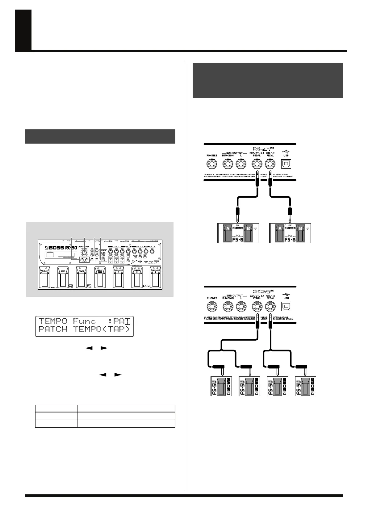
fig.07-070
1.
Press [CTL/EXP PEDAL] to display the pedal settings screen.
fig.07-080d
2.
Press PARAMETER [ ] [ ] to display the pedal
function screen for the pedal whose settings you want to
change.
3.
After using PARAMETER [ ] [ ] to move the cursor to
“SYS” or “PAT” in the upper row of the display, you can then
rotate the PATCH/VALUE dial to select either the system
settings or patch settings as the settings to be used.
* When switching between the system settings and patch settings,
“EXP Func,” “EXP Level Min/Max,” and “EXP Tempo Min/Max”
are together affected.
4.
Repeat Steps 2 and 3 as needed.
5.
Press [EXIT] to return to the Play screen.
This procedure sets the functions for the RC-50’s TEMPO pedal and
UNDO/REDO pedals and for foot switches connected to the CTL 1,2
PEDAL jack and the EXP/CTL 3, 4 PEDAL jack.
* The following shows the correspondence between pedal switch (A/B)
and CTL pedal functions when an FS-6 is connected.
fig.07-090
* When connecting two foot switches with the special connection cable
(Roland PCS-31L; optional, sold separately), the correspondence
between pedal switch and CTL pedal functions is as shown below.
fig.07-100
* If you want to connect foot switches individually, the CTL1 pedal
function and CTL3 pedal function settings are used.
System Settings and Patch Settings
Available Settings
Description
~~: SYS
The system settings are used.
~~: PAT
The patch settings are used.
Setting the Functions for the RC-50’s Pedals
and External Foot Switches (TEMPO/UNDO/
CTL1/CTL2/CTL3/CTL4 Pedal Function)
CTL1CTL2
PCS-31L
WhiteRedWhiteRed
CTL3CTL4
PCS-31L
RC-50_e.book 70 ページ 2009年4月10日 金曜日 午後1時17分
 Loading...