13
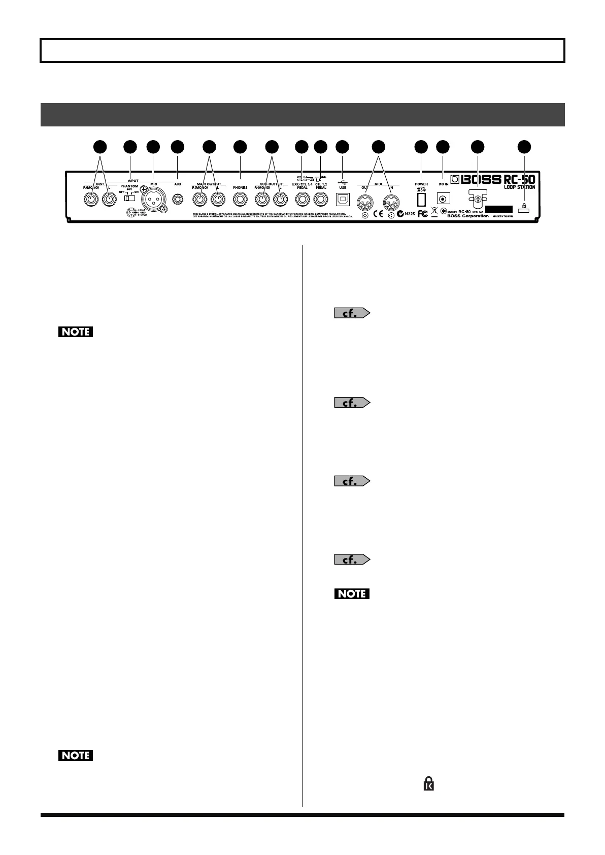
Names of Things and What They Do
fig.00-220
1. INPUT R (MONO)/L Jacks
Connect a guitar, synthesizer, or other such instrument here.
2.
PHANTOM
(Phantom Power)
ON/OFF Switch
This switches the phantom power supplied to the MIC
connector on and off.
Be sure to switch the phantom power off unless there is a
condenser microphone requiring phantom power connected to
the MIC connector. Supplying phantom power to dynamic
microphones, audio playback equipment, and other such devices
may damage your equipment. For more on mic specifications,
read the owner’s manual for the mic you are using.
(RC-50 phantom power: 48 V DC, 10 mA Max)
3. MIC Connector
Connect a microphone here. The RC-50 provides 48-volt
phantom power, allowing you to connect and use phantom
powered condenser mics. You can also use the Flat Amp
Simulator with input from this connector when recording.
4. AUX Jack
A cable can be connected between here and the headphone jack
on a CD or MD player or other such device.
During recording, you can use the Center Cancel and Flat Amp
Simulator functions with input from this connector.
5. MAIN OUTPUT R (MONO)/L Jacks
Connect a guitar amp, monitor speakers, or other such device
here.
6. PHONES Jack
Connect stereo headphones here.
The sounds output from this jack are the same as those output
from the MAIN OUTPUT jacks.
7. SUB OUTPUT R (MONO)/L Jacks
Connect an amp, mixer, or other such device here. You can
assign the input sounds, guide sound, and sounds of the three
phrases either to the MAIN OUTPUT or the SUB OUTPUT
jacks.
The SUB OUTPUT jacks have no level knob. If you want to
adjust the volume level from these jacks, adjust the patch level
(p. 49).
8. EXP/CTL 3,4 PEDAL Jack
You can connect an optional expression pedal (such as the EV-5)
or foot switch (FS-6 or other) here. You can select the function,
for example switching patches, assigned to the connected pedal
or foot switch.
“Pedal Settings” (p. 70)
9. CTL 1,2 PEDAL Jack
Connect a foot switch (FS-6 or other) here. You can select the
function, for example switching patches, assigned to the
connected switch.
“Pedal Settings” (p. 70)
10.
USB Connector
You can connect a computer here using a USB cable and
exchange data between the RC-50 and the computer.
“Chapter 9 Connecting to Computers” (p. 79)
11.
MIDI IN/OUT Connectors
Connect external MIDI devices here to transmit and receive
MIDI data.
“Chapter 8 Using MIDI” (p. 73)
When connecting the USB cable, remove the cover attached to
the USB connector. Leave the cover attached when not using the
USB connector.
12.
POWER Switch
This turns the RC-50’s power on and off.
13.
DC IN (AC Adaptor) Jack
Connect the included adaptor (BOSS PSA-S series, Roland ACI
or ACB series) here.
14.
Cord Hook
Loop the AC adaptor cord around here to prevent the AC
adaptor from being unplugged by accident.
15.
Security Slot ( )
http://www.kensington.com/
Rear Panel
1 2 3 4 6 8 9
10 12 13 14
5 7
11 15
RC-50_e.book 13 ページ 2009年4月10日 金曜日 午後1時17分
 Loading...