Disassembly / Assembly SpaceCover
5
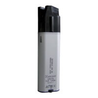
5- 10 SpaceStation, 1.0 gb
1.0
5.8 Processor PCB
Designation Ord. No.
(Only SpaceCover comfort) Processor PCB SPCC . . . . . . . . . . . . . . . . . . . . . . . . . . . 3452 1259
Housing bottom part SPCS . . . . . . . . . . . . . . . . . . . . . . 3452 1208
Housing bottom part SPCC . . . . . . . . . . . . . . . . . . . . . . 3452 1186
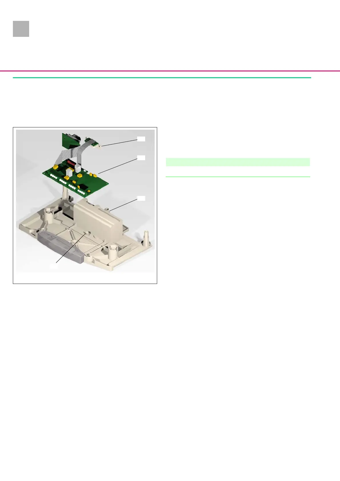
Disassembly
1. Push the contact strip (Abb.: 5 - 9 / Item 1) to the battery
module to the rear and out of the housing bottom part
(Abb.: 5 - 9 / Item 3).
Note
The contact strip is integrated in the processor PCB.
2. Press the release button (Abb.: 5 - 9 / Item 4) in the housing
bottom part carefully to the rear and remove the processor
PCB (Abb.: 5 - 9 / Item 2) out of the housing bottom part.
Abb.: 5 - 9
Legende zu Abb. 5 - 9:
ItemDesignation
1Contact strip
2Processor PCB
3 Housing bottom part
4 Release button
2
3
4
1