Disassembly / Assembly SpaceCom
4
4- 14 SpaceStation, 2.0 gb
2.0
Note
Before the housing back panel is definitely fitted check the insu-
lating hood and the insulating piece for proper fit and the correct
cable layout of the fan cable and of the connecting cable to the
battery contact strip.
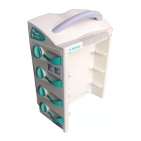
3. Place on the housing back panel (Abb.: 4 - 13 / Item 2) and
fasten it with the two longer screws (Abb.: 4 - 13 / Item 3)
and the eight shorter screws (Abb.: 4 - 13 / Item 4).
Note
Insert the housing back panel on the notches (Abb.: 4 - 13 /
Item 1) at the two connector coverings of the housing and tilt the
back panel in its final position.
Note
Pay attention to the cable connections when placing on the hous-
ing back panel. These must not be squeezed.
Note
Pay attention to the different screw lengths when mounting the
housing back panel. The longer screws are provided for the left-
hand and right-hand upper screw opening.
4. No screw is inserted in the third mounting hole (from the top)
on the right-hand side of the back panel. The hole must be
covered with a cover cap.
4.11 Checks after Repair
1. Check the device to ensure safe functionality of the unit (see
„Device Check“ ➨ S. 2 - 4).
2. Depending on the work carried out the specific steps of the
TSC must be performed (see „Technical Safety Check (TSC)“ ➨
S. 7 - 1).
3. The activities carried out must be recorded in the following
check list.
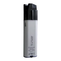
Abb.: 4 - 13
Legende zu Abb. 4 - 13:
ItemDesignation
1 Locking tabs
2 Housing back panel
3 Screw A2 WN 5452 30x16
4 Screw A2 WN 5452 30x9
5 Housing cover cap
6 W-LAN cover
2
6
5
4
3
1
3