Unit Diagnosis / Calibration
2
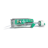
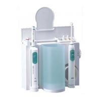
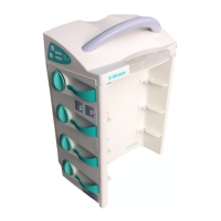
2- 6 SpaceStation, 2.0 gb
2.0
Trouble Shooting
Note
The following trouble shooting cannot be carried out independ-
ently. It is based on the precise observance of the steps for the de-
vice check (see „Device Check“ ➨ S. 2 - 4). From there reference
is made to the corresponding trouble shooting steps.
7 The charge condition of the battery module is dis-
played in the bottom charge condition display of
the operator and status display field of the Space-
Cover comfort
UTS-COM 8 TS 22
8 Connect the SpaceStation with the interface ca-
ble RJ45 cross-over via the Ethernet (RJ45) con-
nection of the SpaceCom to a PC
UTS-COM 9
9 Start the SpaceOnline Program (see „SpaceOnli-
ne“ ➨ S. 1 - 17)
The data of the SpaceStation and the pumps in-
serted is displayed on the PC monitor
UTS-COM
10
TS 20
10 Connect the SpaceStation with the interface ca-
ble RS232 SPCO (crossed) via the RS 232 connec-
tor of the SpaceCom to a PC
UTS-COM
11
11 Start the BCCshow Program (see „BCCshow“ ➨
S. 1 - 19).
The data of the SpaceStation and the pumps in-
serted is displayed on the PC monitor
UTS-COM
12
TS 20
12 Detach or loosen all connections and devices
from the SpaceStation
This step terminates the
device check
GS-
COM
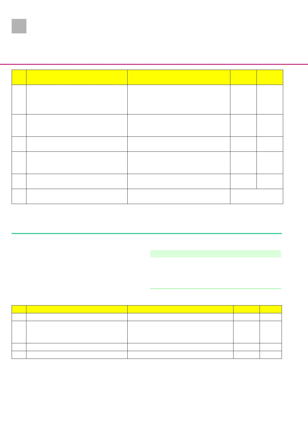
Activity Function If yes If no
Table 2 - 4 Device check SpaceCom (Part 2 of 2)
TS Activity Function If yes If no
1 Replace the module lock UTS 3
2 Check the voltage 12 V (-0.6 V / +3.5 V) DC at the
interface board plug contacts (connection power
supply – interface board)
The voltage is measured TS 4 TS 3
3 Replace power supply UTS 4
4 Replace interface board UTS 4
Table 2 - 5 Trouble shooting (Part 1 of 2)